TP-6137 5/03 81Section 10 Generator and Engine Disassembly/Reassembly
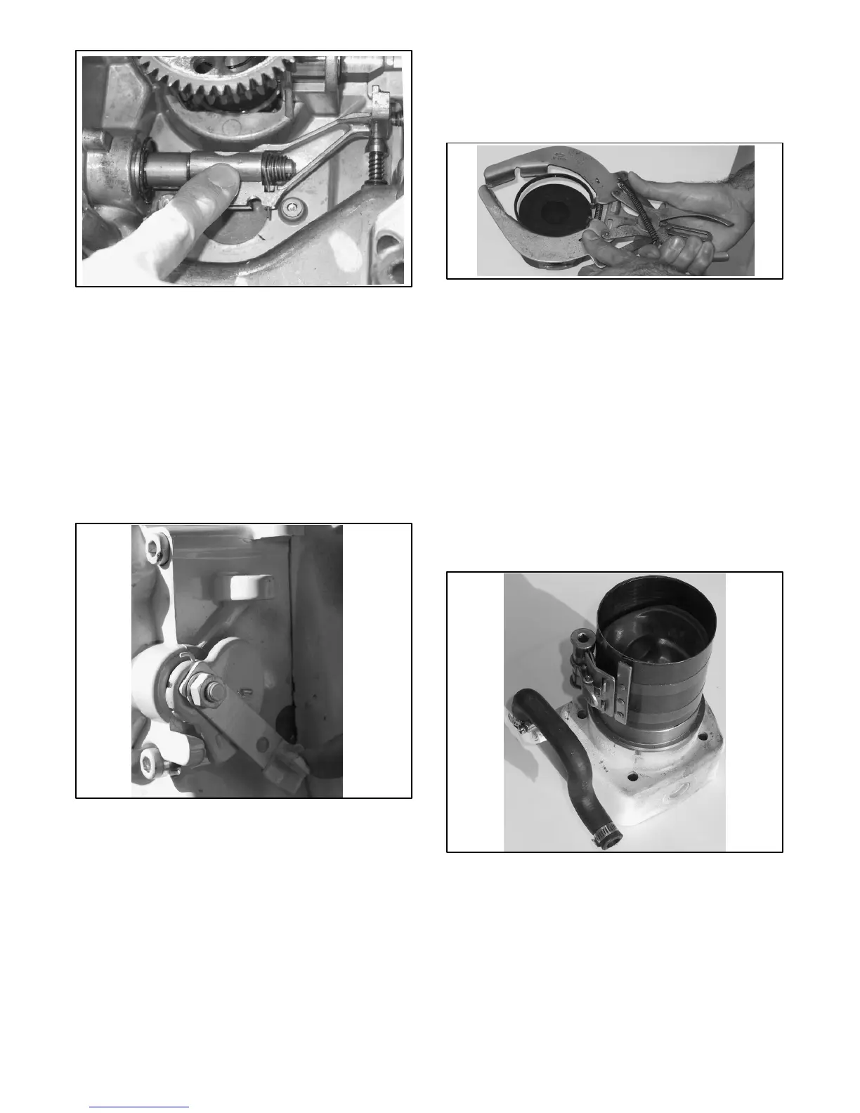
Figure 10-78 Inner Spring
11. Check the speed control shaft performance and
check its springs. The inner spring is correctly set if
it rejects the push of the governor pin. See
Figure 10-78.
12. The outer spring is correctly set when the
accelerator lever is held in position during a higher
engine speed rate. Increase its tension by
changing the position on the ratchet plate. Also,
check its reaction in the opposite direction. See
Figure 10-79.
Figure 10-79 Ratchet Plate
Piston
1. Using a ring expander tool, install the piston rings
so that the “Top Marks” are towards the piston
crown. See Figure 10-80.
Figure 10-80 Piston and Ring Expander Tool
2. Lubricate the rings and the piston skirt.
3. Check that the piston ring gaps are at 120_ offset.
4. Put the cylinder on the bench with its upper side
touching the bench.
Note: Never tap on the piston crown.
Note: Never install the piston from the upper side of the
cylinder because the liner is narrower and lightly
tapered in this position.
5. Compress all of the rings with a ring compressor
tool and drive the piston in the cylinder.
Figure 10-81 Ring Compressor