TP-5982 4/0612 Section 1 Introduction
132
4
5
6
7
8
12
9
10
11
13
14
15
16
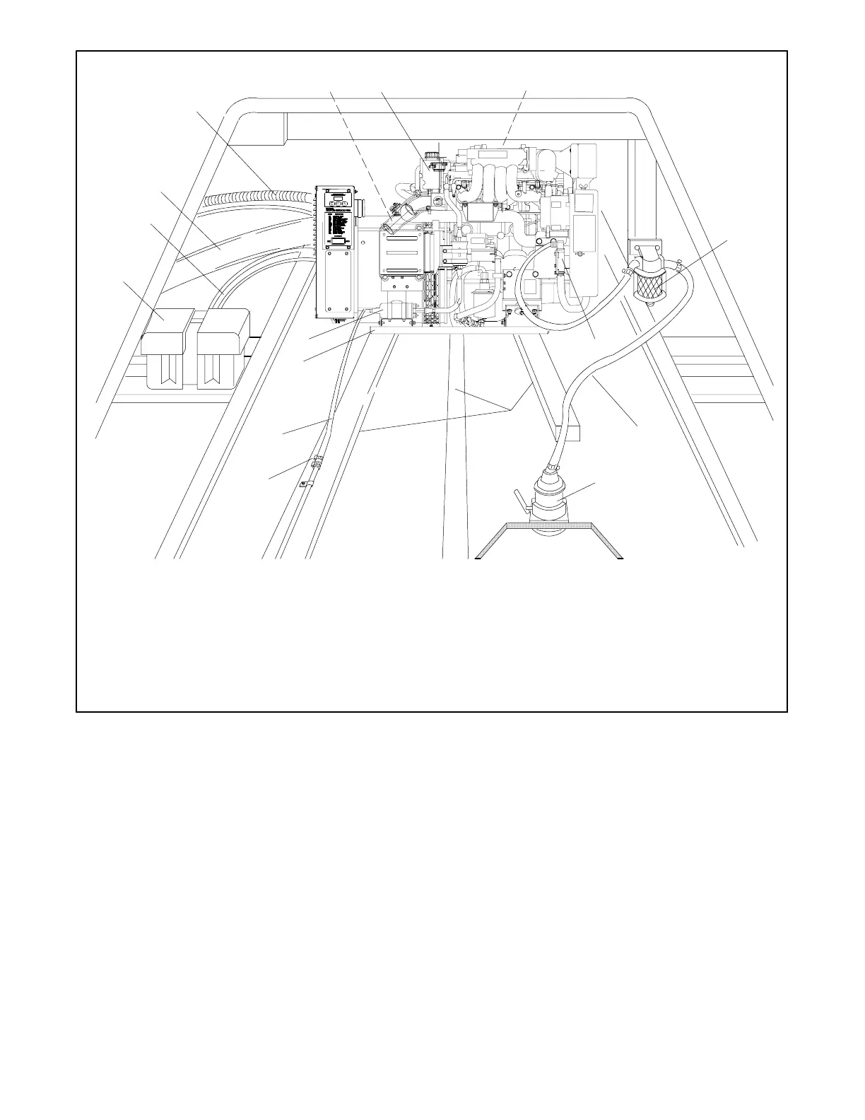
585711
1. Exhaust mixer elbow (exhaust/water outlet)
2. Coolant recovery tank
3. Heat exchanger (not shown)
4. Seawater strainer *
5. Seawater pump (seawater inlet)
6. Seawater line *
7. Seacock *
8. Craft stringers
9. Hose clamps
10. Fuel supply line *
11. Mounting tray
12. Fuel feed pump (fuel inlet) *
13. Battery/battery storage box
14. Battery cables
15. Exhaust hose or exhaust line *
16. Electrical leads (AC output leads/remote start panel leads)
* Indicated components must conform to USCG regulations.
Figure 1-2 Typical Generator Set Location and Mounting (10/13/15EG Model Shown, 13/15EGZ, 5/7.3ECD and
4/6EFCD Models Similar)
Note: See text for complete explanation of installation
requirements.
Note: Use two hose clamps on each end of all flexible
exhaust hose connections.
 Loading...