TP-5982 4/06 27Section 5 Fuel System
5.3.2 15/20C and 12.5/16CF Models
Conform to USCG regulations regarding in-line fuel
filters or strainers. Independently mount the in-line fuel
filter or strainer to the craft’s structure. Ensure
accessibility for servicing without removing permanent
structures.
Note: Fuel filter/strainer installation. Support each
fuel filter and strainer on the engine or boat
structure independent of its fuel-line connections
unless the fuel filter or strainer is inside a fuel
tank.
5.4 Antisiphon Device Installation
Install antisiphon devices when a fuel line section lies
below the highest point of the fuel tank. Install an
antisiphon device as follows:
D Use a spring-loaded check valve (tested to function
with the installation’s siphon head) or an electrically
operated shutoff valve (UL ignition-protected
tested to USCG regulations) that can operate
manually as the antisiphon device.
D Install the check valve above the fuel tank’s highest
point.
D Secure the check valve to the craft’s structure,
ensuring accessibility without removing permanent
structures.
D Locate the fuel-line section between the tank and
check valve above the fuel tank’s highest point.
Install an electric shutoff valve at the fuel tank’s
fuel-withdrawal fitting.
D Wire the shutoff valve to open whenever cranking
or running the generator set.
Antisiphon holes drilled into fuel dip tubes within the fuel
tank are unreliable antisiphon devices because they
become ineffective when restricted by dirt or gum.
5.5 Fuel Pump Lift and Fuel
Consumption
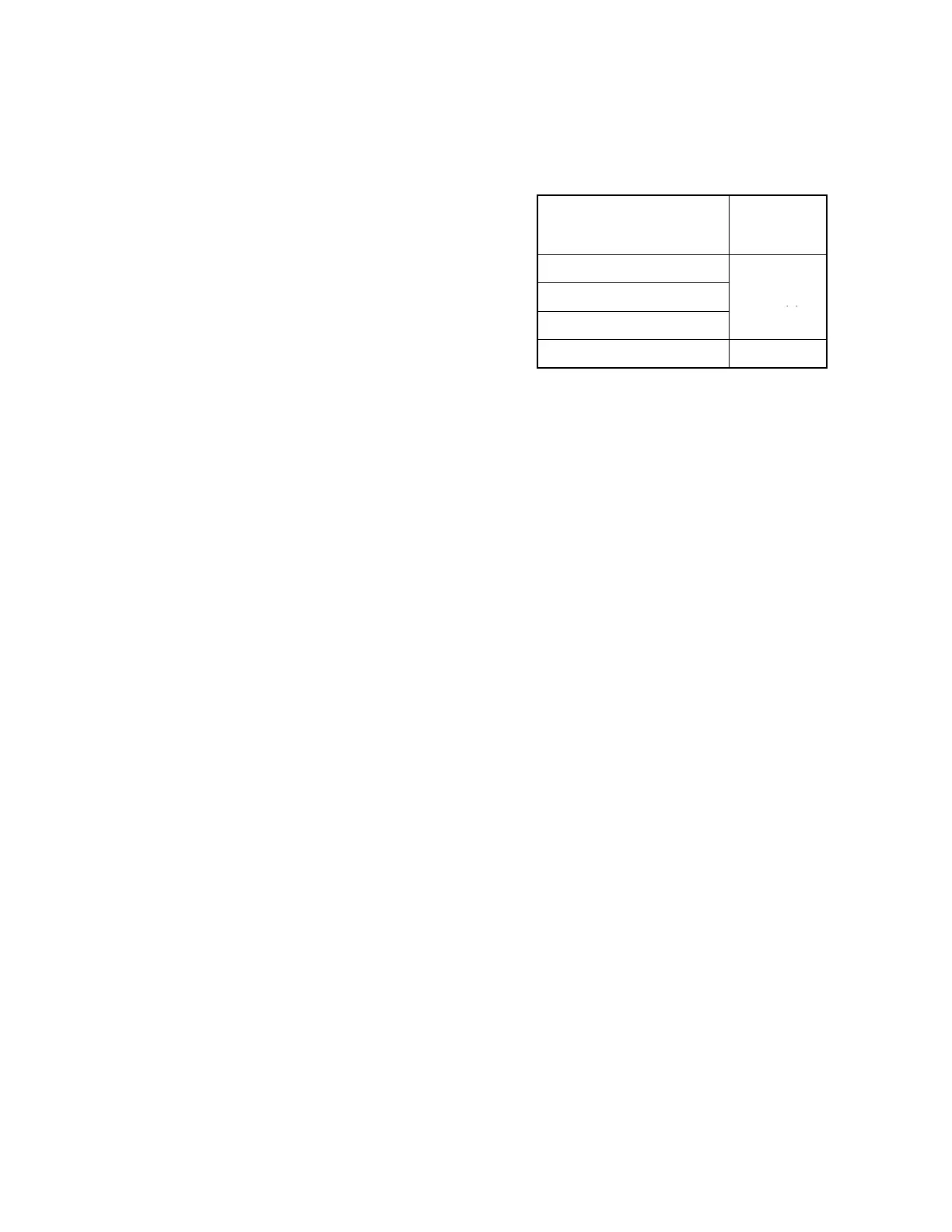
See Figure 5-7 for fuel pump lift capabilities. Consult
current generator set specification sheets for generator
set fuel consumption rates.
Model
Fuel Pump
Lift
m (ft.)
5/7.3E and 4/6EF
5/7.3ECD and 4/6EFCD
0.9 (3)
10/13/15EG and 13/15EGZ
15/20C and 12.5/16CF 1.2 (4)
Figure 5-7 Fuel Pump Lift Capabilities (Max.)
 Loading...