TP-6195 1/04 27Section 6 Installation
Figure 6-2 gives the exhaust flow and temperature at
rated load. Mount the generator set so that the hot
exhaust does not blow on plants or other combustible
materials.
Exhaust System 60 Hz 50 Hz
Exhaust flow at rated kW, m
3
/min. (cfm)
8.5RES 3.3 (115) 2.7 (96)
12RES 3.8 (135) 3.2 (113)
Exhaust temperature at rated kW, dry
exhaust, _C(_F)
816 (1500)
Figure 6-2 Exhaust Flow and Temperature
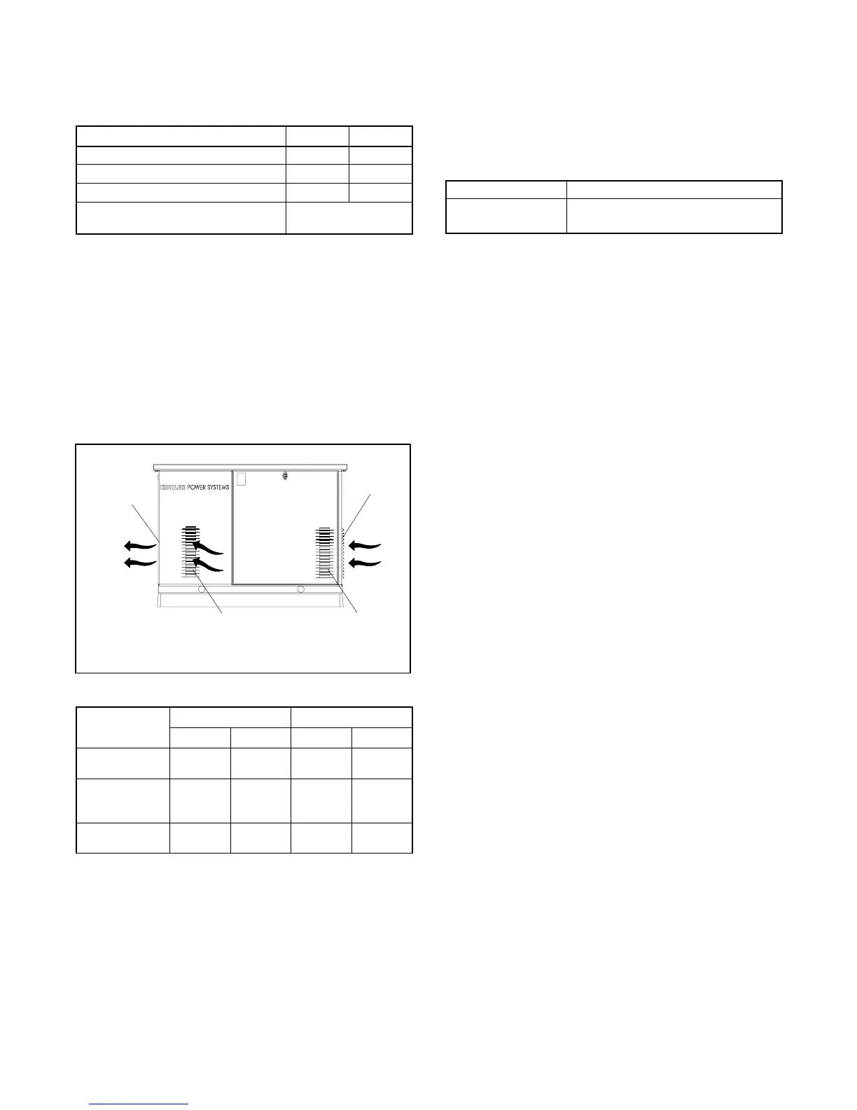
6.6 Air Requirements
The generator set requires correct air flow for cooling
and combustion. The inlet and outlet openings in the
sound enclosure provide the cooling and combustion
air. Figure 6-3 shows the locations of the cooling air
intake and exhaust vents. Inspect the air inlet and outlet
openings inside and outside the housing to ensure that
the air flow is not blocked.
tp6195
2
1. Exhaust outlet
2. Alternator air intake (both sides)
3. Engine air intake
3
1
3
Figure 6-3 Cooling Air Intake and Exhaust
8.5RES 12RES
Requirements
60 Hz 50 Hz 60 Hz 50 Hz
Cooling air,
m
3
/min. (cfm)
26.9 (950) 22.4 (790) 26.9 (950) 22.4 (790)
Total inlet air
requirement,
m
3
/min. (cfm)
27.8 (980) 23.2 (820) 28.0 (990) 23.4 (825)
Combustion air,
m
3
/min. (cfm)
0.94 (33.4) 0.8 (28.0) 1.1 (39.2) 0.9 (32.6)
Figure 6-4 Cooling Air Requirements
6.7 Power Supply
Utility power must be supplied to the generator set
location. Provide a 110- or 120-volt outlet connected to
the utility power supply for the battery charger
(standard) and carburetor heater (optional). Figure 6-5
lists the battery charger power requirements.
Input Requirement
Rated AC voltage 90--135 VAC, 50/60 Hz
Current draw 1.6 amp at full output
Figure 6-5 Battery Charger Power Requirements
6.8 Fuel System
The generator set operates using natural gas or LP
vapor fuel. The multi-fuel system allows conversion
from natural gas to LP vapor (or vice-versa) in the field
while maintaining emissions-standard compliance. A
trained technician or authorized distributor/dealer can
convert the fuel system. Generator sets with multi-fuel
systems are CARB- and EPA-certified for both natural
gas and LP vapor fuels.
6.8.1 Fuel Supply
Comply with local, state, and federal codes regarding
the correct s torage of fuel. Because of variable climates
and geographical considerations, c ontact an authorized
service distributor/dealer for fuel system planning and
installation.
Figure 6-1 shows the location of the fuel inlet
connection. Bring the fuel supply lines through the rear
access opening. Use flexible sections to prevent fuel
line breakage caused by vibration. Remove the housing
end panel and hold the fuel solenoid valve with a wrench
when tightening the fuel connections. Protect all fuel
lines from machinery or equipment contact, adverse
weather conditions, and environmental damage.
Verify that the output pressure from the primary gas
utility (or LP tank) pressure regulator is 1.7--2.7 kPa
(7--11 in. water column) and that the utility gas meter
flow rate is sufficient to supply the generator set plus all
other gas-consuming appliances. Figure 6-8 shows the
flow rate required for the generator set. Figure 6-6 lists
 Loading...


