TP-6880 10/14 53Section 4 DC2 Controller Operation
Section 4 DC2 Controller Operation
4.1 DC2 Generator Set/ Transfer
Switch Controller
Model RESVL generator sets are equipped with the
DC2 generator set/transfer switch controller.
Model RESV generator sets are equipped with the
RDC2 generator set/transfer switch controller. See
Section 3 for RDC2 controller operation information.
The DC2 controls the following power system
components:
D Model 8RESVL, 10RESVL, or 12RESVL generator
set
D Model RXT Automatic Transfer Switch (ATS)
D Load Control Module ( LCM) or load shed kit
D Programmable Interface Module (PIM)
DC2 controller features include:
D Two-line x 16 character backlit digital display with
adjustable contrast
D OFF, AUTO, RUN, and EXERCISE generator set
control buttons
4.2 Controls and Indicators
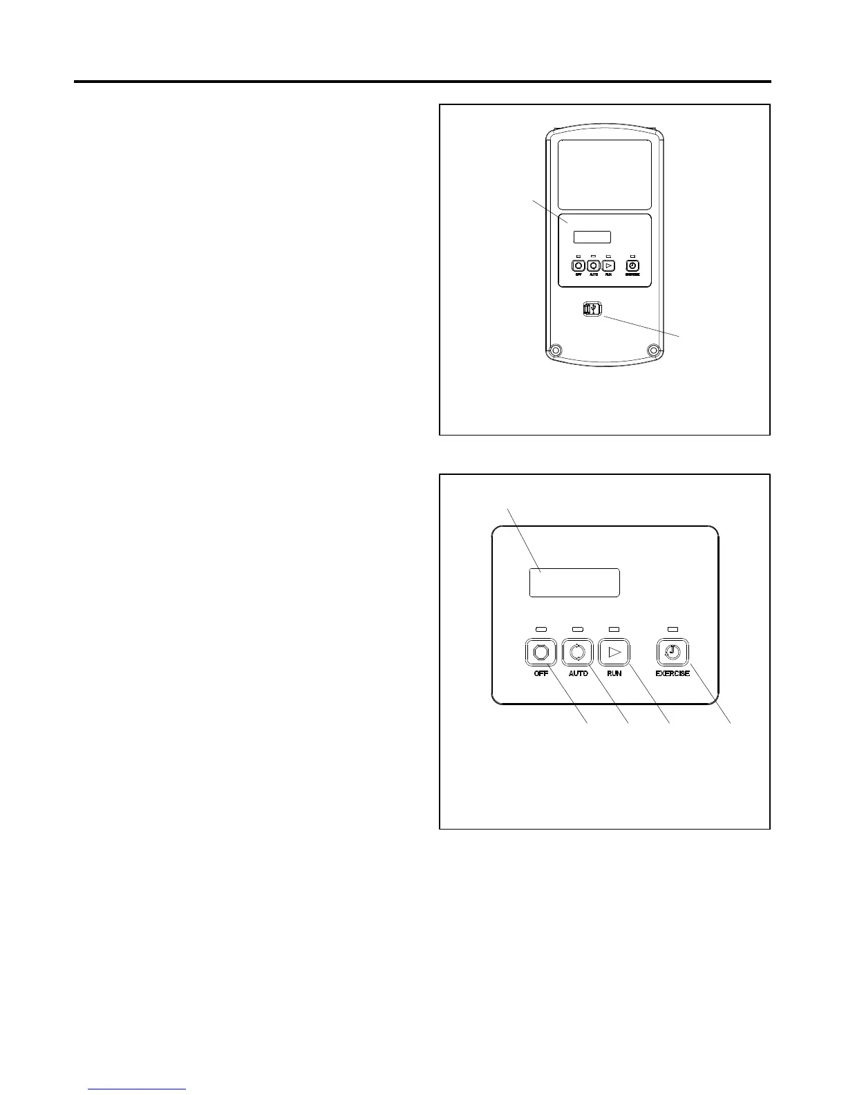
Figure 4-1 illustrates the DC2 controller. See Figure 4-2
for details of the controller’s user interface.
1. User Interface
2. USB port (mini-B); see Section 6.2.
1
2
GM77569
Figure 4-1 DC2 Controls and Indicators
1. 2-line LCD display
2. EXERCISE button
3. RUN button and LED
4. OFF button and LED
5. AUTO button and LED
1
4 35 2
GM77569
Figure 4-2 DC2 User Interface