22 TT-1625 7/17
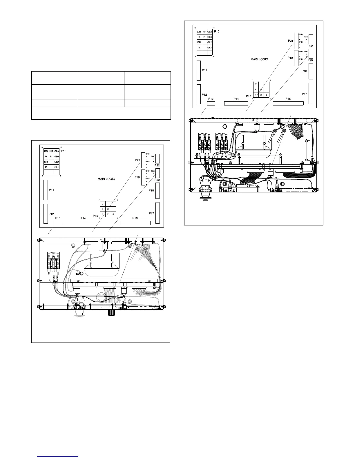
DEC 550 Controller. Figure 33 s hows the
RS-485 connections and Figure 34 shows the
DEC 550 controller with P20 location.
DEC 6000 Controller. Figure 33 shows the
RS-485 connections and Figure 35 shows the
DEC 6000 controller with P20 location.
P20
Connector
Circuit Board
Designation
Wire
Designation
P20-1 GND Shield
P20-2 + White
P20-3 -- Black
Note: When using RS-485 communication cable, connect the
“shield” wire at either end but not at both ends.
Figure 33 DEC 550 and DEC 6000 Controllers P20
RS-485 Connections
TT-1377
1. Main circuit board (top view)
2. P21 for KBus RS-485 communication connection
3. P20 for RSA III RS-485 communication connection
4. Main logic (microprocessor)/communication circuit board
1
3
4
2
Figure 34 DEC 550 Controller R S-485 Connections
TP-6750
1. Interconnect circuit board (top view)
2. P21 for PGEN communication connection
3. P20 for RSA III RS-485 communication connection
4. Main logic (microprocessor)/communication circuit board
1
3
4
2
Figure 35 DEC 6000 Controller R S-485 Connections