Do you have a question about the Kohler MPAC 1500 and is the answer not in the manual?
Warnings about accidental generator set starting and precautions to prevent it.
Details hazards associated with high voltage and moving parts, emphasizing safety measures.
Covers electrical grounding and handling procedures to prevent electrocution.
Highlights risks from short circuits, safe servicing practices, and electrostatic discharge prevention.
Instructions for connecting the controller's logic board, including input/output and communication ports.
Covers setting system parameters, time/date, exerciser, and functional tests before operation.
Procedures for testing manual contactor operation, voltage, frequency, and phasing compatibility.
Verifies controller LEDs and tests the automatic transfer switch functionality.
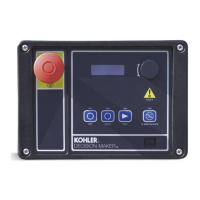
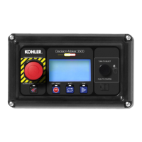
Describes the display, LEDs, pushbuttons, and navigation through screens and menus.
Explains the main screen, status messages, and detailed operational sequences for different transition models.
Covers system tests, troubleshooting warnings/faults, and procedures for resetting data and parameters.
Guides users on accessing and navigating the main screen and various view screens for system information.
Explains how to view recorded events and track maintenance data for troubleshooting and system history.
Covers viewing settings for exerciser, prime power, system, source, time delays, inputs/outputs, alarms, and communications.
Covers DIP switch settings, source naming, and initial setup procedures.
Details factory settings for system parameters, voltage/frequency sensing, and various time delays.
Includes exerciser scheduling, prime power, load control, source setup, communications, and three-source systems.
Covers password management, system calibration, and data reset procedures.
Describes serial, Ethernet, and USB port connections and Modbus communication protocols.
Details setting up serial and Ethernet communication parameters and managing data files via USB.
Emphasizes the importance of preventive maintenance, safety precautions, and general inspection guidelines.
Details weekly generator set exercises, monthly control system tests, and general external/internal inspections.
Provides a schedule of recommended maintenance tasks for electrical, control, and general equipment conditions.
Introduces available hardware options, their current draw, and mounting procedures.
Details I/O modules, alarm functions, DIP switches, and the external battery supply module.
Covers heaters, TVSS, supervised transfer switches, current sensing kits, and load shed accessories.
Describes the user interface cover, logic disconnect switch, and monitoring program software.
| Brand | Kohler |
|---|---|
| Model | MPAC 1500 |
| Category | Controller |
| Language | English |


