TP-6714 4/10 113Section 8 Accessories
8.8 Transient Voltage Surge
Suppressor (TVSS)
A transient voltage surge suppressor (TVSS) is
available for the transfer switch. Installed on the Normal
source side, the TVSS protects the system from voltage
surges, preventing damage to household loads. The
TVSS resets automatically. See Figure 8-19 for TVSS
specifications. See Figure 8-20 for the typical TVSS
assembly location inside the ATS enclosure.
Because of space limitations in the smaller enclosures,
the following models can include either an enclosure
heater or a surge suppressor (TVSS), but not both:
Model KCS 30--200 Amps
Model KSS 40--225 Amps
TVSS Specifications
Surge current 100 kA per phase
Let-through voltage
890 V @ 3 kA
1200 V @ 10 kA
Figure 8-19 TVSS Specifications
1
GM69824
1. TVSS assembly
Figure 8-20 TVSS Location, Typical
8.8.1 Diagnostic LEDs
Red and green indicators on each Transient Voltage
Surge Suppression (TVSS) module indicate protection
status and TVSS condition (good or needs
replacement). See Figure 8-21 and Figure 8-22.
Note: All leads must be connected and power applied
for the LEDs to illuminate.
If the red indicator is on, the TVSS no longer provides
protection. Replace the TVSS module. See
Section 8.8.3 for replacement instructions.
Green
LED
Red
LED
Status
ON OFF
AC power is present and protection
is provided.
OFF ON
AC power is present but the TVSS
module needs replacement. The
remote indication changes state.
OFF OFF
AC power or ground is missing:
Verify that wire connections are
correct.
Make sure that circuit breaker is
engaged.
Check panel for power.
Figure 8-21 TVSS Diagnostic Indication
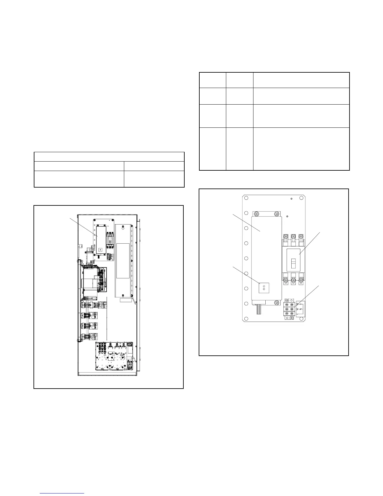
3
GM70493
1. Surge suppressor
2. TVSS status indicators
3. Circuit breaker
4. Auxiliary contact terminal block
2
4
1
Figure 8-22 TVSS Assembly, Typical
8.8.2 TVSS Remote Status Indicator
A customer-supplied indicator for the optional transient
voltage surge suppressor (TVSS) can be connected to
provide remote indication when the TVSS needs to be
replaced. The contact changes state when the TVSS
module needs replacement.
Connect customer-provided indicators or alarms to the
normally open (NO) or normally closed (NC) auxiliary

 Loading...


