TP-6714 4/1012 Section 1 Installation
1.1.1 Logic Board Input and Output
Connections
Logic board terminal strip TB1 has two programmable
inputs and two programmable outputs. See Figure 1-1
for the connector location.
Note: For bypass/isolation switches, input 1 is factory-
connected to the Bypass Contactor Disable
circuit.
Note: For service entrance switches, input 1 is factory-
connected to the transfer inhibit circuit.
Each input has a signal and a return connection. The
outputs are C form contacts with ratings of
500 mA @ 120 VAC. See Figure 1-2 for the
connections. Use #12--24 AWG wire and tighten the
connections to 0.5 Nm (4.4 in. lbs.).
See Section 8.4 for instructions to connect to optional
input/output modules.
The controller logic board’s programmable inputs and
outputs can be assigned to the functions shown in
Section 5.12. Refer to the I/O functions shown in
Figure 5-18 and Figure 5-19 for planning and
connections. You will need to assign functions to the
programmable inputs and outputs through the controller
interface using the Setup Menu—Set Inputs/Outputs
later.
6431
Input 1A
Input 1B
Input 2A
Input 2B
Output 1 NC
Output 1 C
Output 1 NO
Output 2 NC
Output 2 C
Output 2 NO
TB1
NC = normally closed
NO = normally open
C = common
12
6
1
7
Figure 1-2 Logic Board Input and Output
Connections to TB1
1.1.2 Communication Connections
See Section 6 for instructions to connect to the
controller’s RS-485 serial port or Ethernet port for
Modbus communication. See Section 6.4 for
instructions to use the USB port for file transfer.
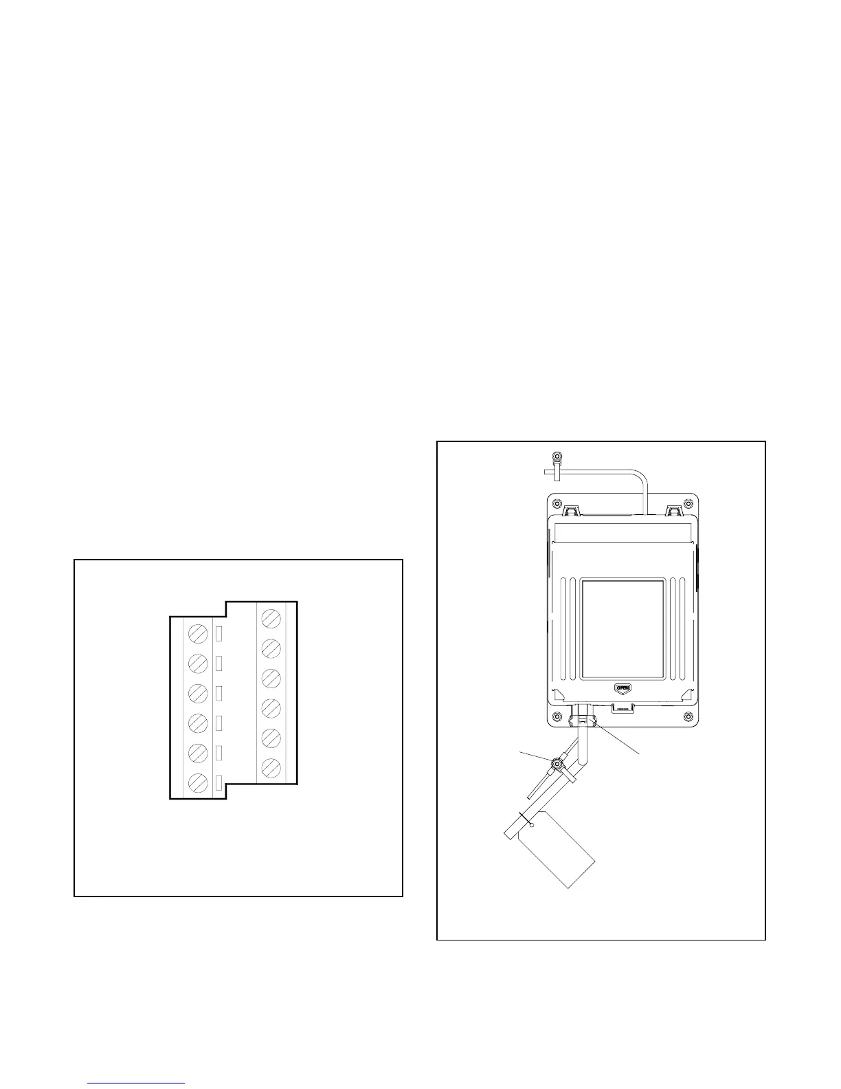
1.1.3 Controller Connection
Verify that the contactor harness is connected at the
controller base (or at the logic disconnect switch, if
equipped). See Figure 1-3.
Note: Verify that the power is disconnected before
connecting or disconnecting the contactor
harness.
1.1.4 Controller Ground
Verify that the grounding wire is connected from the
controller’s lower left mounting stud to the enclosure.
This connection provides proper grounding that does
not rely upon the door hinges.
1
1. Contactor Harness Connection
2. Ground Connection
2
Figure 1-3 Contactor Harness and Controller
Ground Connections

 Loading...


