TP-6714 4/10 107Section 8 Accessories
Section 8 Accessories
8.1 Introduction
This section describes the hardware options that will
interface with the MPACt 1500 controls. The following
accessories are available:
D Standard I/O module
D High Power I/O module
D Alarm Module with preferred source and Chicago
alarm functions
D Supervised transfer control switch
D External battery module
D Current monitoring
D Load shed module
D User interface cover
D Line-to-neutral voltage monitoring
D Logic disconnect switch
D Monitoring software
D Digital meter: V, A, kW, VA, VAR, PF, and Hz
8.2 Accessory Modules
The transfer switch uses a standard bus system for
connecting accessory modules to the controller. This
bus incorporates a standard serial communication
interface for passing data back and forth between the
main logic board and the assemblies on the expansion
bus.
The mounting kit holds up to five optional modules. The
maximum total current draw is 300 mA. See Figure 8-1.
If an External Battery Module is installed, there is no
current restriction. The External Battery Module, if
used, must be the last board on the bus.
Module Current Draw Specifications, mA
Alarm Module 75
Standard I/O Module 75
High Power I/O Module 100
Figure 8-1 Option Board Types
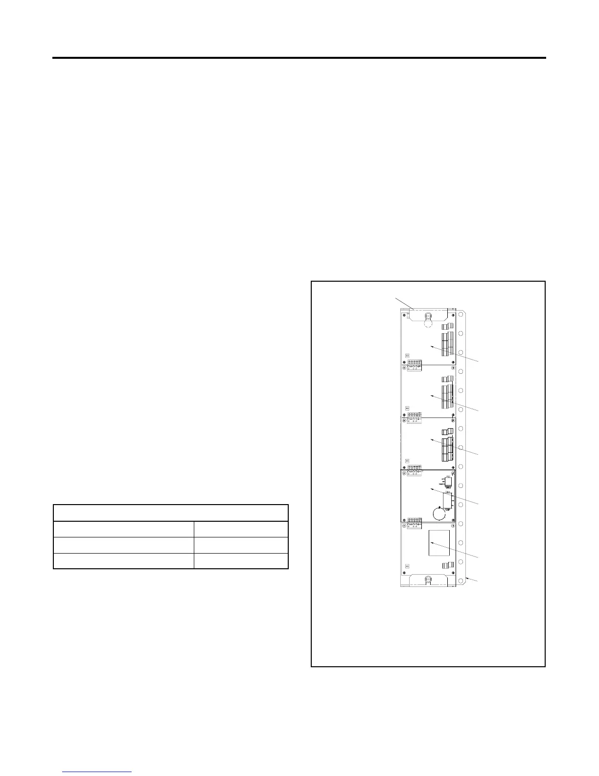
8.3 Accessory Module Mounting
Mount the accessory modules on the module mounting
plate. Starting at the end of the module mounting
assembly nearest the cable connection, install any I/O
modules first, then install the alarm board, if used. The
external battery module, if used, must be the last
module. See Figure 8-2. The alarm board has a fixed
Modbus address = 5.
Note: Some models may have the I/O module
assembly installed with the cable connection end
pointing to the side or the bottom. Regardless of
the actual orientation of the assembly, the I/O
modules must be installed closest to the cable
connection, followed by the alarm module and
then the external battery module, if used.
1. Cable connection (defined as the TOP regardless of
orientation)
2. I/O modules (if equipped)
3. Alarm module (if equipped)
4. External battery module (must be last, if equipped)
5. Mounting plate
1
GM46258
3
5
2
2
2
4
Figure 8-2 Module Mounting

 Loading...


