TP-6714 4/10 109Section 8 Accessories
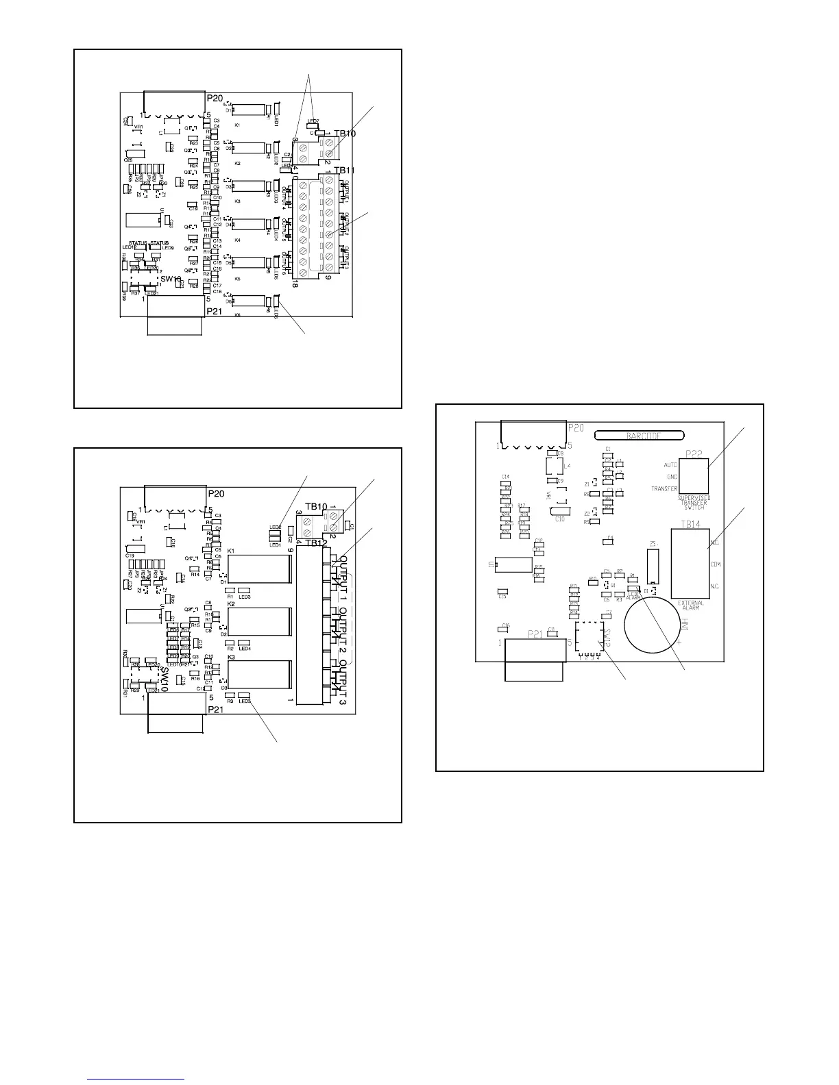
1. Input LEDs 7 and 8 for inputs 1 and 2
2. Input connector (see Figure 8-7)
3. Output connector
4. Output LEDs 1--6
1
GM41093
2
3
4
Figure 8-8 Standard I/O Module
1. Input LEDs 1 and 2
2. Input connector (see Figure 8-7)
3. Output connector
4. Output LEDs 3--5 for outputs 1, 2, and 3
2
GM42186
1
3
4
Figure 8-9 High-Power I/O Module
8.5 Alarm Module
The functions provided by this board are:
D 90 dB Audible alarm (any alarm function can be
programmed to trigger the audible alarm)
D Chicago alarm operation
D Preferred source selection
D Supervised transfer control (supervised transfer
control switch required)
D Connection for external alarm
The alarm board is equipped with a 90 dB audible alarm.
The audible alarm can be set to sound under selected
fault conditions through the Common Alarm Setup
Screen.
The alarm board has a fixed address = 5.
1. Supervised Transfer Switch Connection, P22
2. External Alarm Connection, TB 14
3. Alarm Indicator, LED1
4. DIP Switches
1
GM40764
2
3
4
Figure 8-10 Alarm Module

 Loading...


