TP-6714 4/10108 Section 8 Accessories
8.4 Input/Output (I/O) Modules
Two types of input/output modules are available. The
standard I/O Module has two inputs and six outputs.
The high-power I/O module has two inputs and three
outputs. See Figure 8-3 and Figure 8-4 for I/O module
specifications.
Inputs
Available Inputs 2
Input Definition Contact Closure
Current 5mAMax
Connection Type Terminal Strip
Wire Size #14-24 AWG
Max Distance 700 feet
Outputs
Outputs Available 6
Contact Type Form C (SPDT)
Contact Voltage Rating
2A@30VDC
500 mA @ 125 VAC
Connection Type Terminal Strip
Wire Size #14-24 AWG
Figure 8-3 Standard Input/Output Module
Inputs
Available Inputs 2
Input Definition Contact Closure
Current 5mAMax
Connection Type Terminal Strip
Wire Size #14-24 AWG
Max Distance 700 feet
Outputs
Outputs Available 3
Contact Type Form C (SPDT)
Contact Voltage Rating
12 A @ 24 VDC
12 A @ 250 VAC
10 A @ 277 VAC
2 A @ 480 VAC
Connection Type Terminal Strip
Wire Size #14-24 AWG
Environmental Specifications
Temperature -- 4 0 °Cto85°C(--40°F to 185 °F)
Humidity 35% to 85% noncondensing
Figure 8-4 High-Power Input/Output Module
Use 14-24 AWG cable to connect to input and outputs.
Each output is a form C SPDT contact.
LEDs on the module circuit board light to indicate that
each input or output is active.
Note: Each I/O module must have unique address.
Use the address DIP switches on the I/O module to
assign a unique (different) address to each module as
shown in Figure 8-5. Assign addresses in order from 1
to 4. An LED for each DIP switch lights to indicate that
the switch is closed.
The alarm module’s fixed address is 5. The battery
module’s fixed address is 6.
Use the Set Inputs/Outputs screen to assign input and
output functions. See Section 5.12 for instructions.
DIP Switch
Address
1 2
Off Off 1
On Off 2
Off On 3
On On 4
Figure 8-5 Address DIP Switch Settings
Both switches OFF
Address=1 shown
Figure 8-6 Address DIP Switches
refGM41093
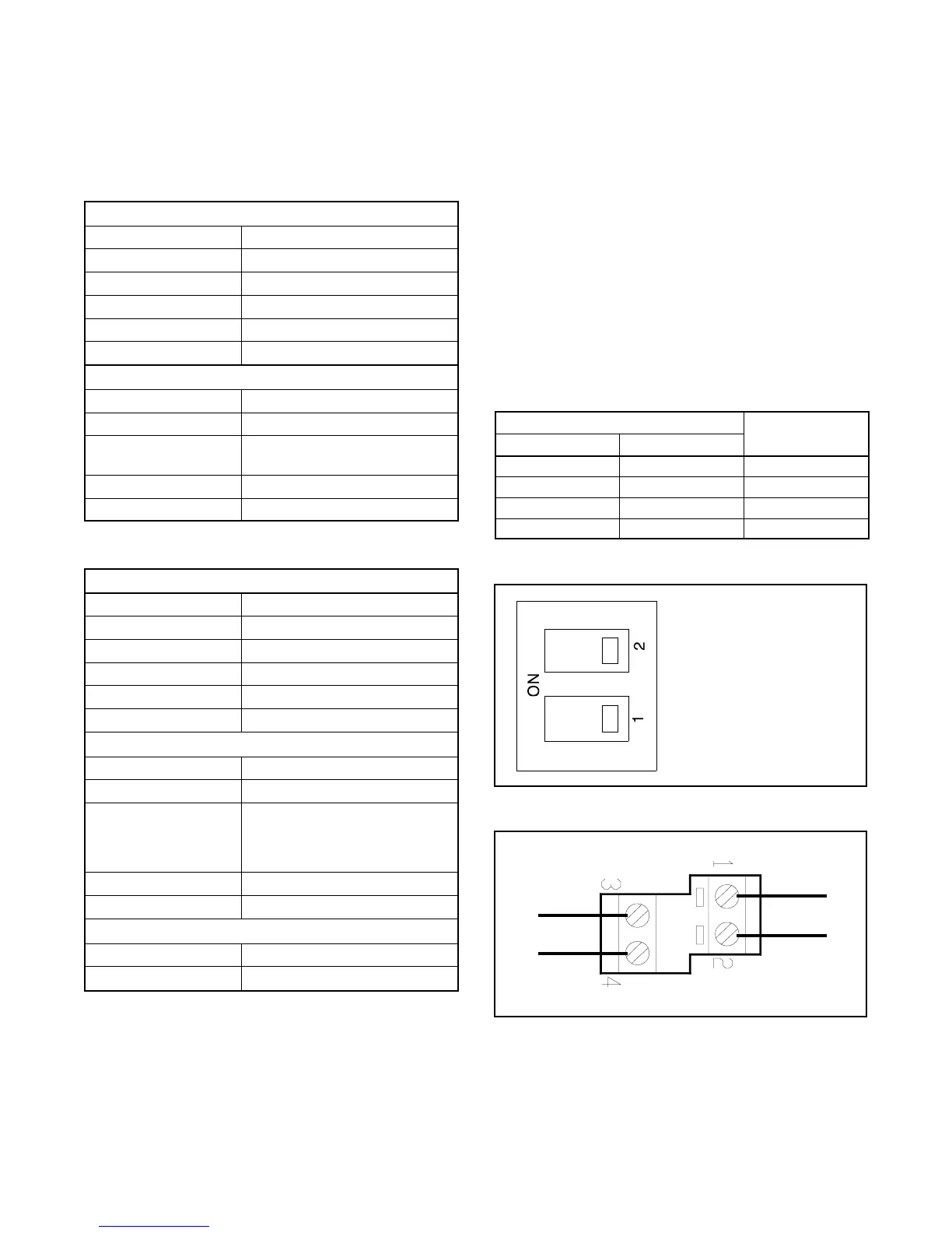
INPUT 1
INPUT 2
Figure 8-7 I/O Module Input Connections
(TB1 or TB10)

 Loading...


