TP-6714 4/10 95Section 6 Communications
6.2.2 Ethernet Connections
The transfer switch c an be connected to a building’s
ethernet network to communicate with personal
computers connected to the same subnet. Work with
the building’s network manager to obtain an IP address
and subnet mask information.
Ethernet Port. The ethernet port is a standard RJ-45
female plug on the controller’s main logic board. See
Figure 6-1 for the location of the Ethernet port. Use
Category 5e or better cable to connect the controller to
the building’s network. The ethernet connection allows
the controller to communicate with a personal computer
on the network to run Monitor III Software or other
Modbus applications.
Note: For an ethernet connection, obtain an IP address
and subnet mask number from the local system
administrator.
Use the Setup menus to assign a port number, IP
address, and subnet mask number from the controller’s
front panel. The controller may have a default IP
address assigned at the factory for test purposes. See
Figure 6-4. Change the IP address to an address
owned by the user. See Section 5.16 for i nstructions to
set the communication parameters.
The series 1500 controller does not operate as a
Modbus-to-Ethernet converter for other devices in a
network. For multiple device networks connected to the
personal computer through the Ethernet, use a
Modbus-to-Ethernet converter for the other devices in
the network. See Figure 6-5 and instruction sheet
TT-1405, provided with the converter, for connection
instructions.
The controller can communicate with up to eight (8)
simultaneous TCP/IP (ethernet) connections. If anyone
attempts to establish a ninth connection, the first
connection that was established will be dropped. These
eight connections do not include the RS-485 serial port.
In the extreme case, eight users may be communicating
with the controller via TCP/IP network connections and
another may be communicating through the serial port,
for a total of nine communication channels. As the
controller is asked to communicate with more and more
outside devices, its performance will slow down.
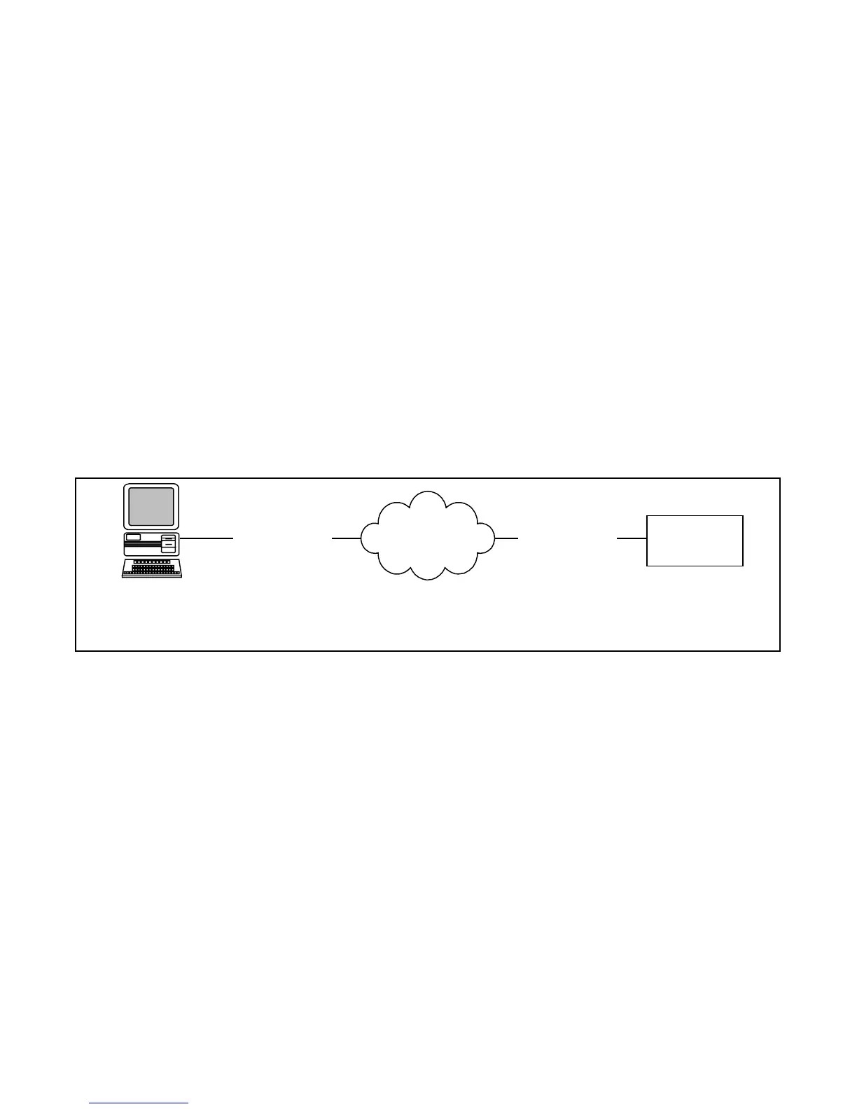
PC with network
interface card
IP xx.xx.xx.02
Ethernet
Network
ATS 1500
Controller IP
xx.xx.xx.03
Modbusr TCP/IP
Category 5e
Modbusr TCP/IP
Category 5e
Note: The PC and the ATS must be on the s ame subnet.
Note: A crossover cable can be used to connect the PC
to the ATS controller through the Ethernet port.
Figure 6-4 Remote Network (Ethernet) Connection

 Loading...


