63
Disassembly/Inspection and Service
24 690 06 Rev. J KohlerEngines.com
Remove Inner Bafes and Breather Cover
Inner (valley) bafes are attached at one corner using
same fasteners as breather cover.
1. Remove screws securing inner bafes.
2. Remove both inner bafes.
3. Remove two remaining screws holding breather
cover to crankcase.
4. Pry under protruding edge of breather cover with a
screwdriver to break RTV or gasket seal. Do not pry
on sealing surfaces as it could cause damage
resulting in leaks. Most engines use a formed gasket
rather than RTV sealant.
5. Remove breather cover and gasket (if used).
6. Remove breather lter from chamber.
7. Remove screw, breather reed retainer and breather
reed.
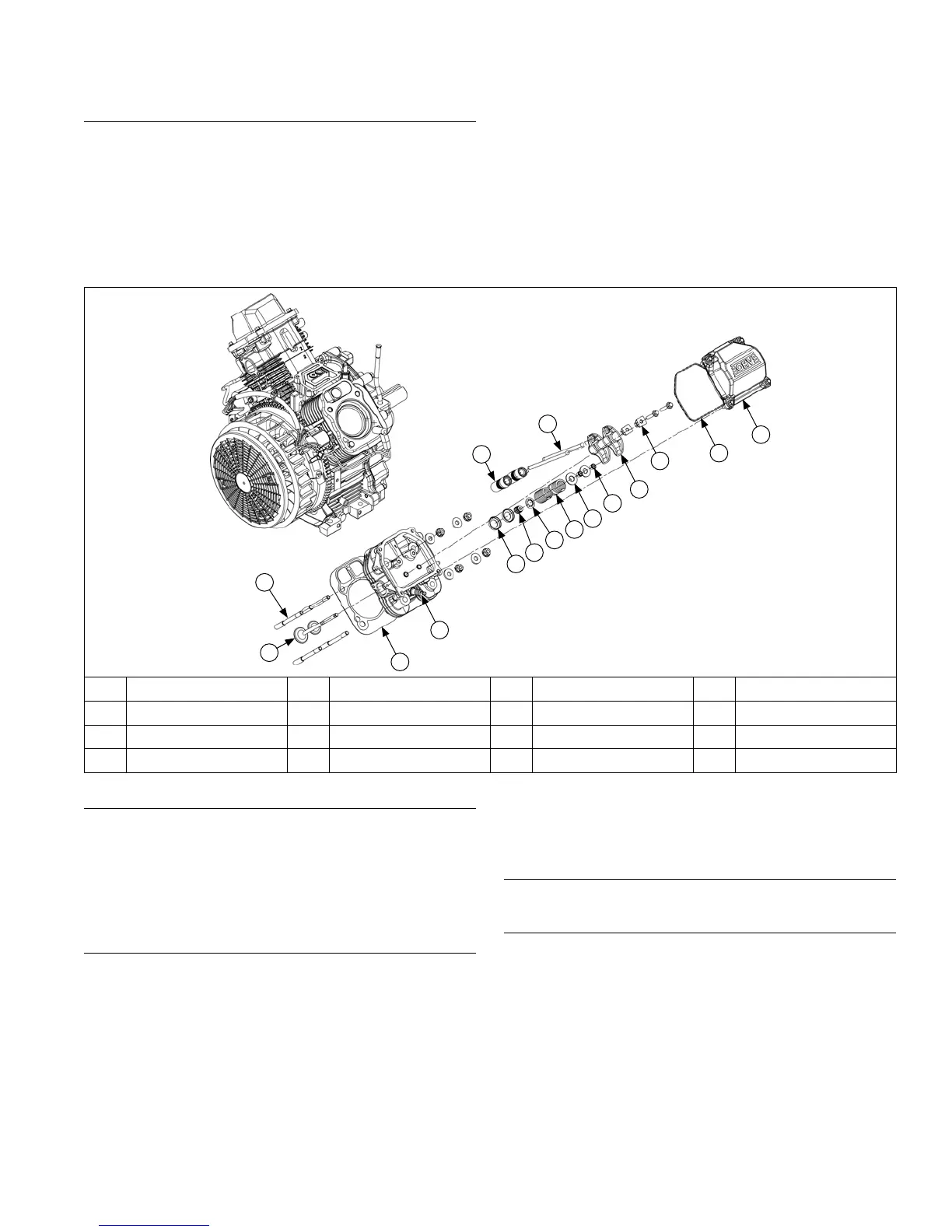
Cylinder Head Components
B
C
D
E
G
K
F
H
I
J
L
M
N
O
P
A
A Valve B Stud C Gasket D Spark Plug
E Cap F Valve Stem Seal G Hydraulic Lifter H Retainer
I Valve Spring J Valve Spring Retainer K Push Rod L Valve Keeper
M Rocker Arm N Rocker Arm Pivot O Valve Cover O-ring P Valve Cover
Remove Intake Manifold
1. Remove screws securing intake manifold to cylinder
heads. Note which screws hold wiring clamps.
2. Remove intake manifold and intake manifold gaskets
(aluminum intake manifolds) or O-rings (plastic
intake manifolds).
3. Leave wiring harness attached to manifold.
Remove Valve Covers
Three valve cover designs have been used. Earliest
type used a gasket and RTV sealant between cover and
sealing surface of cylinder head. Second type had a
black O-ring installed in a groove on underside of cover
and may have metal spacers in bolt holes. Latest design
uses a brown O-ring, and bolt holes spacers are molded
in place.
1. Remove screws securing each valve cover. Note
position of any attached brackets or lifting straps.
2. Remove valve covers, valve cover gaskets or
O-rings and any brackets or lifting straps. Note
which side of engine has oil ll and or fuel pump
valve cover.
Remove Spark Plugs
Remove spark plug from each cylinder head.
Remove Cylinder Heads and Hydraulic Lifters
NOTE: Cylinder heads are retained using either screws
or nuts and washers on studs. Do not
interchange or mix components, as cylinder
heads may have different machining, unique to
each fastening method.
NOTE: Exhaust lifters are located on output shaft side
of engine while intake lifters are located on fan
side of engine. Cylinder head number is
embossed on outside of each cylinder head.
 Loading...