Install Fuel Pump
WARNING
Explosive Fuel can cause res and severe
burns.
Do not ll fuel tank while engine is hot or
running.
Gasoline is extremely ammable and its vapors can
explode if ignited. Store gasoline only in approved
containers, in well ventilated, unoccupied buildings,
away from sparks or ames. Spilled fuel could ignite if
it comes in contact with hot parts or sparks from
ignition. Never use gasoline as a cleaning agent.
NOTE: Pulse style fuel pumps may be made of metal or
plastic. If a new fuel pump is being installed,
make sure orientation of new pump is consistent
with removed pump. Internal damage may occur
if installed incorrectly.
1. Install pulse style fuel pump and lines as an
assembly. Connect pulse line to crankcase vacuum
tting or valve cover, whichever source is used.
2. Install fuel pump using screws. Torque screws to
2.3 N·m (20 in. lb.).
Install Carburetor
WARNING
Explosive Fuel can cause res and severe
burns.
Do not ll fuel tank while engine is hot or
running.
Gasoline is extremely ammable and its vapors can
explode if ignited. Store gasoline only in approved
containers, in well ventilated, unoccupied buildings,
away from sparks or ames. Spilled fuel could ignite if
it comes in contact with hot parts or sparks from
ignition. Never use gasoline as a cleaning agent.
One-Barrel Carburetor Models
1. Install a new carburetor gasket. Make sure all holes
align and are open.
2. Install carburetor, throttle linkage and governor lever
as an assembly. If a plastic intake manifold is used
and carburetor is equipped with a fuel solenoid,
attach ground lead to carburetor mounting screw.
3. Torque carburetor mounting screws to
6.2-7.3 N·m (55-65 in. lb.).
Two-Barrel Carburetor Models
1. Use a new carburetor gasket. Make sure all holes
align and are open.
2. Apply Loctite
®
242
®
to shorter (inner) set of threads
of any removed studs.
3. Assemble carburetor gasket and carburetor to intake
manifold, and start any removed studs. Use two
ange nuts locked ange to ange and tighten each
stud until bottomed/tight.
4. Connect ground lead and fuel solenoid lead as
equipped.
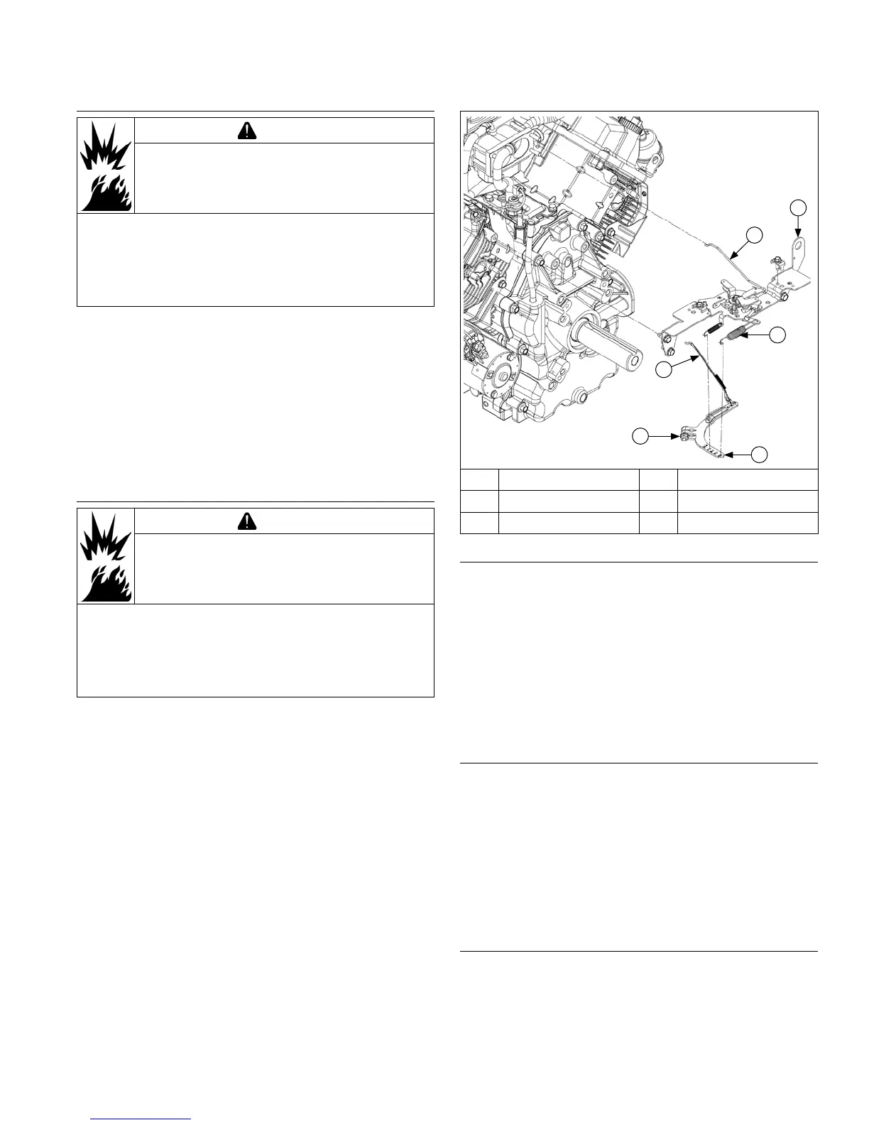
Control Bracket Components
E
F
D
C
B
A
A Choke Linkage B Control Bracket
C Spring D Governor Lever
E Nut F Throttle Linkage
Install External Governor Controls
1. Install governor lever onto governor cross shaft.
2. Make sure throttle linkage is connected to governor
lever and throttle lever on carburetor.
3. Move governor lever toward carburetor as far as it
will go (wide-open throttle) and hold in position.
4. Insert a nail into hole on cross shaft and rotate shaft
counterclockwise as far as it will turn, then torque
nut to 6.8 N·m (60 in. lb.).
5. Reconnect lead wire to fuel shut-off solenoid if
equipped.
Install Throttle & Choke Controls
1. Connect choke linkage to carburetor and choke
actuator lever.
2. Mount main control bracket, and air cleaner support
bracket (if used) to cylinder heads using four screws.
Torque screws to 10.7 N·m (95 in. lb.) into new
holes, or 7.3 N·m (65 in. lb.) into used holes.
3. Connect governor spring from main control bracket
to appropriate hole in governor lever as indicated in
applicable chart. Note that hole positions are
counted from pivot point of governor lever.
Install Oil Sentry
™
(if equipped)
1. Apply pipe sealant with Teon
®
(Loctite
®
PST
®
592™
or equivalent) to threads of Oil Sentry
™
switch and
install it into breather cover. Torque to 4.5 N·m
(40 in. lb.).
2. Connect wire lead (green) to Oil Sentry
™
terminal.
Reassembly
8524 690 06 Rev. J KohlerEngines.com
 Loading...