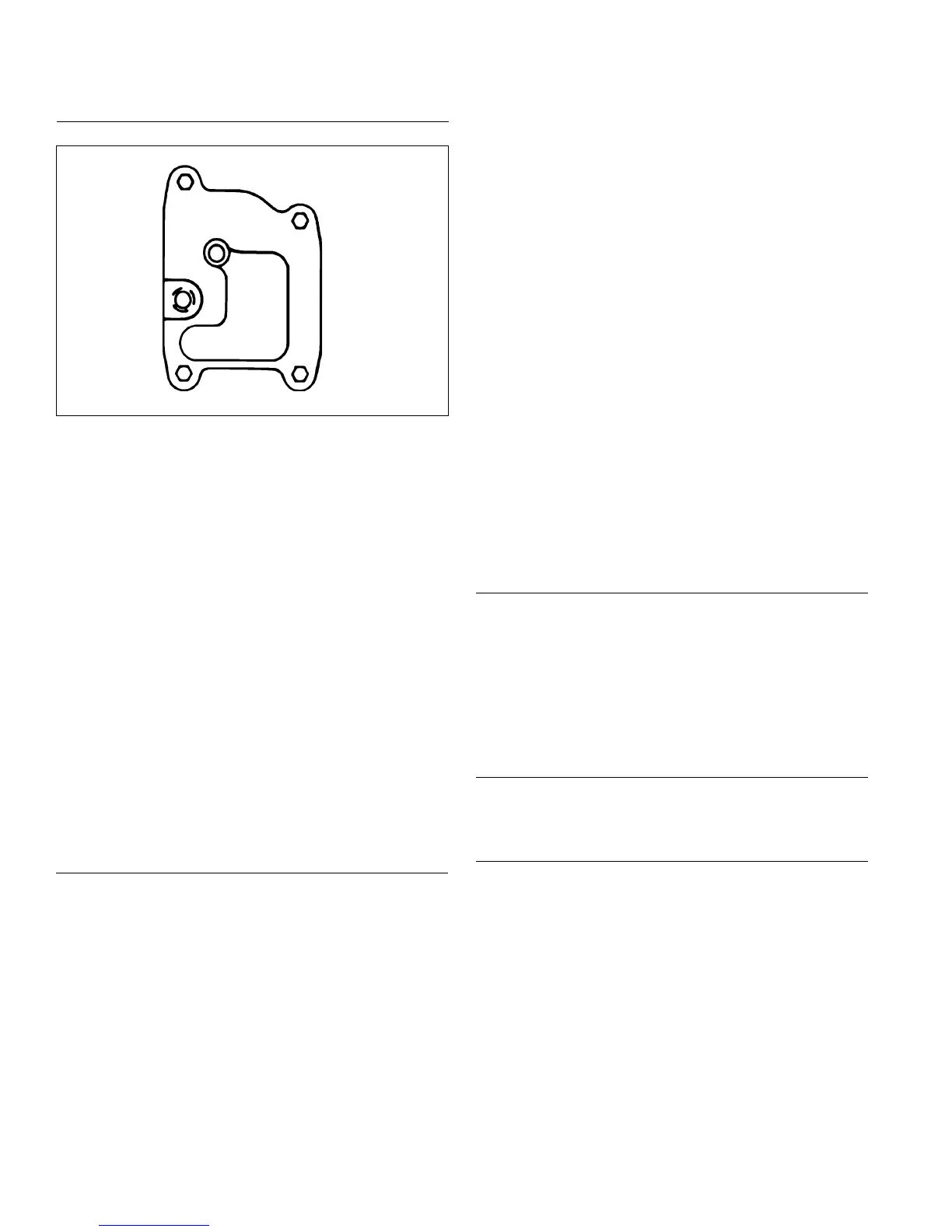
Install Breather Cover and Inner Bafes
Breather Cover Torque Sequence
1
2
3
4
RTV sealant was used on early models between
breather cover and crankcase. A gasket with imprinted
sealant beads is now used and recommended. Install as
follows:
1. Be sure sealing surfaces of crankcase and breather
cover are clean of old gasket material or RTV
sealant. Do not scrape surfaces as this could result
in leakage.
2. Check to make sure there are no nicks or burrs on
sealing surfaces.
3. Install breather reed and breather reed retainer onto
crankcase and secure with screw. Hold assembly in
line when tightening. Torque screw to 3.9 N·m
(35 in. lb.).
4. Insert breather lter into position in crankcase. Make
sure no lter strands are on sealing surface.
5. Install new breather gasket.
6. Carefully position breather cover on crankcase.
Install rst two screws at positions shown and nger
tighten at this time.
7. Install inner bafes using two remaining screws and
nger tighten. Do not torque screws at this time; they
will be tightened after blower housing and outer
bafes are installed.
Install Blower Housing and Outer Bafes
NOTE: Do not completely tighten screws until all items
are installed to allow shifting for hole alignment.
1. Connect plug to key switch in blower housing (if
equipped).
2. Slide blower housing into position over front edge of
inner bafes. Start a few screws to hold it in place.
On two-barrel carburetor models, lift debris shield up
above mounting surface, as blower housing is
installed. Make sure ground lead, fuel solenoid lead,
and oil pressure switch leads are accessible and in
proper position.
3. Position outer bafes and loosely start mounting
screws. M6 screws go into back of cylinders. Short
M5 screws go into lower holes closest to blower
housing. Short screw on oil lter side is also used to
mount wire harness clip. Be sure any wire harnesses
or leads are routed out through proper offsets or
notches, so they will not be pinched between blower
housing and bafes.
4. If rectier-regulator was not removed, attach ground
wire or metal grounding bracket for rectier-
regulator, using silver colored screw and washer, to
lower blower housing hole.
5. Tighten all shrouding fasteners. Torque blower
housing screws to 6.2 N·m (55 in. lb.) in a new hole,
or to 4.0 N·m (35 in. lb.) in a used hole. Torque
shorter M5 side bafe screws to 4.0 N·m (35 in. lb.).
Torque upper M5 side bafe screws (into cylinder
head) to 6.2 N·m (55 in. lb.) in a new hole, or to 4.0
N·m (35 in. lb.) in a used hole. Torque two rear M6
bafe mounting screws to 10.7 N·m (95 in. lb.) in a
new hole, or to 7.3 N·m (65 in. lb.) in a used hole.
6. If an overlapping style ywheel screen is used,
attach it to supports or ywheel. For a metal ywheel
screen, apply Loctite
®
242
®
to screw threads (M6)
and torque to 9.9 N·m (88 in. lb.). Torque plastic
screen mounting screws (M4) to 2.2 N·m (20 in. lb.).
7. Torque breather cover screws to 7.3 N·m (65 in. lb.)
in sequence shown.
Reconnect Rectier-Regulator
1. Install rectier-regulator in blower housing, if
removed previously, then connect rectier-regulator
ground lead with washer and silver screw through
eyelet as shown. If a grounding bracket is used,
secure with lower mounting screw and washer,
against outer side of rectier-regulator.
2. Install B+ terminal/lead into center position of
rectier-regulator plug and connect plug to rectier-
regulator.
SMART-SPARK
™
Module
On engines with SMART-SPARK
™
, reinstall SAM module
to blower housing or cylinder bafe. Do not overtighten
retaining screws.
Install Electric Starter Motor
NOTE: If engine uses a side mount mufer on starter
side, be sure to tie wires close to starter to avoid
contact with hot exhaust parts.
1. Install starter motor using two screws. Some inertia-
drive starters have a pinion cover and spacers on
starter bolts.
2. Torque screws to 15.3 N·m (135 in. lb.).
3. On models with a solenoid shift starter, connect
leads to solenoid.
Reassembly
84
24 690 06 Rev. JKohlerEngines.com
 Loading...