Section 11
Reassembly
11
11.5
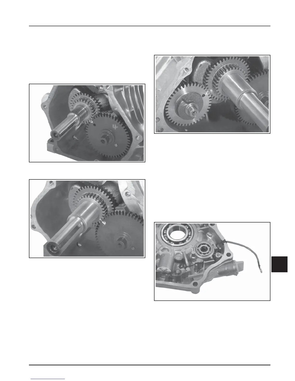
Figure 11-18. Oil Sentry
™
Gauge Mounting and
Lead Routing Details.
2. Install the balance shaft, aligning the timing mark
(hole) with the timing mark (dimple) on the
larger crankgear. See Figure 11-17.
3. Rotate the crankshaft to TDC so the timing mark
(dimple) on crankgear (smaller gear) is in the 4
o’clock position. Install the camshaft into the
crankcase, aligning the timing marks on the two
gears. See Figures 11-15 and 11-16.
NOTE: Timing mark is the hole on CS4, CS6 and
the small dimple on CS8.5-12.
Figure 11-17. CS8.5-12. Aligning Balance Shaft and
Crankgear Timing Marks.
Install Governor Assembly
The governor gear assembly is located inside the
closure plate. If servicing was performed or the
governor was removed, reassemble as per procedures
under Governor Reassembly in Section 10.
Install Oil Sentry
™
Gauge
1. Mount the Oil Sentry
™
gauge into the closure
plate using two M6x1.0 hex flange screws. Route
the wire lead and seat the grommet in the cutout
as shown in Figure 11-18.
Figure 11-15. CS4, CS6. Aligning Crankshaft and
Camshaft Timing Marks.
Figure 11-16. CS8.5-12. Aligning Crankshaft and
Camshaft Timing Marks.
Install Balance Shaft (CS8.5-12, If So
Equipped)
1. Position the crankshaft so the timing mark
(dimple) on the larger crankgear is in the 8
o’clock position.