Section 11
Reassembly
11
11.21
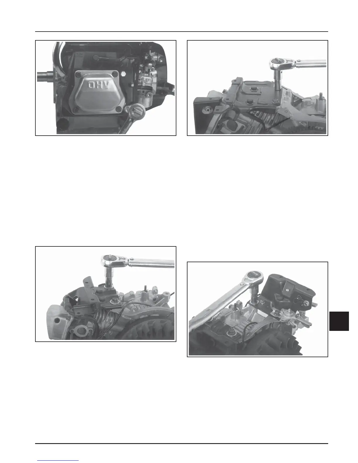
Figure 11-80. CS8.5-12. Torquing Screws.
Install Fuel Tank Supports (If So
Equipped), Throttle Lever, Wiring
Harness, Ignition Switch, and Oil Sentry™
Control Module
CS4, CS6, CS8.5 (spec. 92xxxx), CS10, CS12:
1. Attach the left fuel tank support to the crankcase
bosses with the two hex flange screws and flat
washers under the heads (CS4 and CS6 only).
Torque screws to:
CS4, CS6: 22-26 N·m (195-230 in. lb.)
CS8.5 (spec. 92xxxx), CS10, CS12: 27-31 N·m
(237-274 in. lb.)
Figure 11-82. CS8.5 (spec. 92xxxx), CS10, CS12.
Mounting Left Fuel Tank Support.
2. Assemble the right fuel tank support and
attached electrical components* to the crankcase
bosses. Mount the throttle control bracket off the
flywheel side screw as shown in Figures 11-83
and 11-84. Install a flat washer under the head of
screw on PTO side only. Torque screws to:
CS4, CS6: 22-26 N·m (195-230 in. lb.)
CS8.5 (spec. 92xxxx), CS10, CS12: 27-31 N·m
(238-274 in. lb.)
*The fuel tank support may have the ignition
switch, wiring harness, oil sentry control
module, starter and warning light attached
(based on model/spec. involved).
Figure 11-81. CS4, CS6. Mounting Left Fuel Tank
Support.
Figure 11-83. CS4, CS6. Mounting Right Fuel Tank
Support.