Section 11
Reassembly
11
11.23
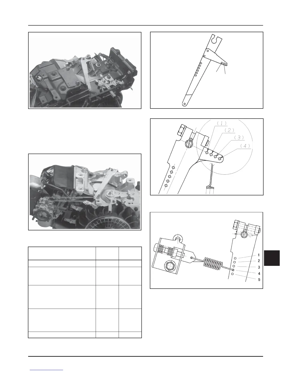
Figure 11-87. CS8.5 (spec. 92xxxx), CS10, CS12.
Governor Lever Installation.
3. Connect the throttle link and the shorter end of
dampening spring, from the top down, into the
hole(s) in long end of governor lever as shown in
Figures 11-86, 11-87, and 11-88.
Figure 11-88. CS8.5 (spec. 95xxxx), CS10, CS12.
Governor Linkage Connected to Governor Arm.
Figure 11-89. CS4, CS6. Spring Hole Position.
Model
Hole
Position
CS4 All models 2
1
2
Figure
Number
11-89
CS6 All models except listed
specs.
CS6 Specs: 911510
11-89
11-89
1
2
CS8.5All models except listed
specs.
CS8.5Spec: 921509
CS8.5Spec: 951511
CS10 All models except listed
specs.
CS10 Specs: 931512, 931612
931614, 931615
11-90
11-90
11-90
3
1
2
11-90
11-91
3
4
Figure 11-90. CS8.5 (spec. 92xxxx), CS10, CS12.
Spring Hole Position.
Figure 11-91. CS8.5 (spec. 95xxxx). Spring Hole
Position.
CS10 Spec: 931618 211-91