Section 11
Reassembly
11
11.25
Connect Electrical Leads and Install
Electric Starter (If So Equipped)
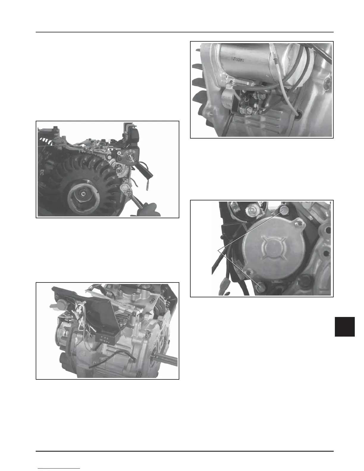
CS8.5 (spec. 92xxxx), CS10, CS12 with Inertia
Drive Starters
1. Mount the electric starter, with the control panel
and solenoid attached, onto the crankcase. Install
and torque the two hex flange screws to 30 N·m
(265 in. lb.). Leave the three cover panel screws
out at this time.
Figure 11-94. CS8.5 (spec. 92xxxx), CS10, CS12.
Reconnect Solenoid/Wiring Harness Lead.
CS8.5 (spec. 95xxxx), CS10, CS12 with Solenoid
Shift Starters
1. Align and mount the electric starter motor to the
crankcase. Install and torque the two hex flange
screws to 30 N·m (265 in. lb.). See Figure 11-95.
Figure 11-92. CS8.5 (spec. 92xxxx), CS10, CS12.
Installing Electric Starter.
2. Connect the electrical leads for the Oil Sentry
™
,
ignition module, keyswitch, solenoid, and starter.
Attach the red/white wire harness lead to the
solenoid terminal opposite the terminal
containing the starter lead.
Figure 11-95. Solenoid Shift Starter Mounting.
2. Connect the electrical leads for the Oil Sentry
™
,
ignition module, keyswitch, solenoid, and starter.
Attach the red/white wire harness lead to the
spade terminal of solenoid. Attach the red
harness lead with the ring terminal, to the main
(upper) terminal on the solenoid that is attached
to the battery cable. Secure the wires together and
out of the way using the beaded tie.
Figure 11-93. CS8.5 (spec. 92xxxx), CS10, CS12.
Reconnect Electrical Leads.
Mounting
Screws