8.25
Section 8
Electrical System and Components
8
Plunger
Pushed “In”
VOM Meter
Leads
12 volt Test Leads
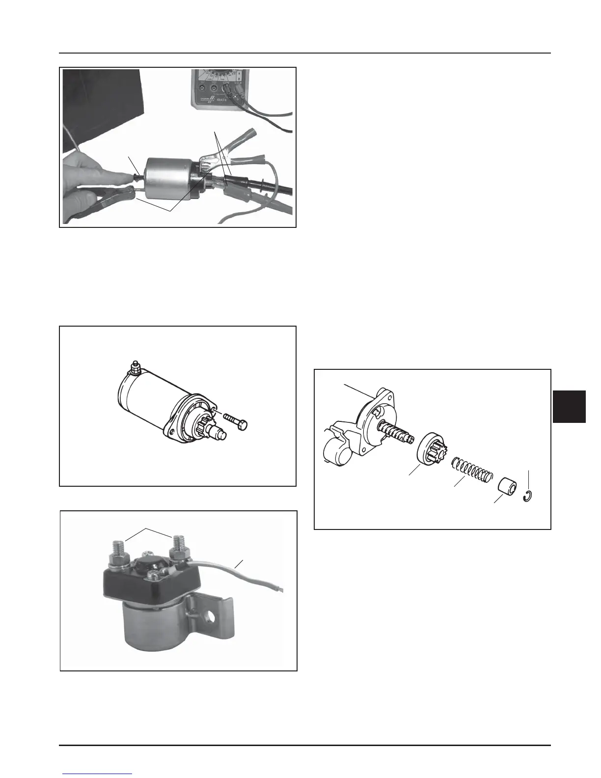
Figure 8-31. Testing Hold-In Coil/Solenoid Contact
Continuity.
Inertia Drive Electric Starters
This subsection covers the operation, troubleshooting,
and repair of the inertia drive, permanent magnet
electric starter.
Figure 8-32. Inertia Drive Starter.
Operation
When power is applied to the starter, the armature
rotates. As the armature rotates, the drive pinion
moves out on the splined drive shaft and into mesh
with the flywheel ring gear. When the pinion reaches
the end of the drive shaft, it rotates the flywheel and
cranks the engine.
When the engine starts, the flywheel rotates faster
than the starter armature and drive pinion. This moves
the drive pinion out of mesh with the ring gear and
into the retracted position. When power is removed
from the starter, the armature stops rotating and the
drive pinion is held in the retracted position by the
anti-drift spring.
Starter Drive Service
Every 300 hours of operation (or annually, whichever
occurs first), clean and lubricate the splines on the
starter drive shaft. If the drive pinion is worn, or has
chipped or broken teeth, it must be replaced.
It is not necessary to completely disassemble the
starter to service the drive components. Service the
drive as follows:
Figure 8-34. Drive Components.
1. Remove the starter from the engine.
2. Push back the spring holder (collar) to expose the
retaining ring on the armature shaft, which
secures the drive components. Remove the
retaining ring using either of the Kohler retaining
ring removal tools.
Drive Pinion
Spring
Retaining
Ring
Spring
Holder (Collar)
Post Terminals
Red/White
Lead
Figure 8-33. Solenoid Details.