93
Reassembly
62 690 13 Rev. A KohlerEngines.com
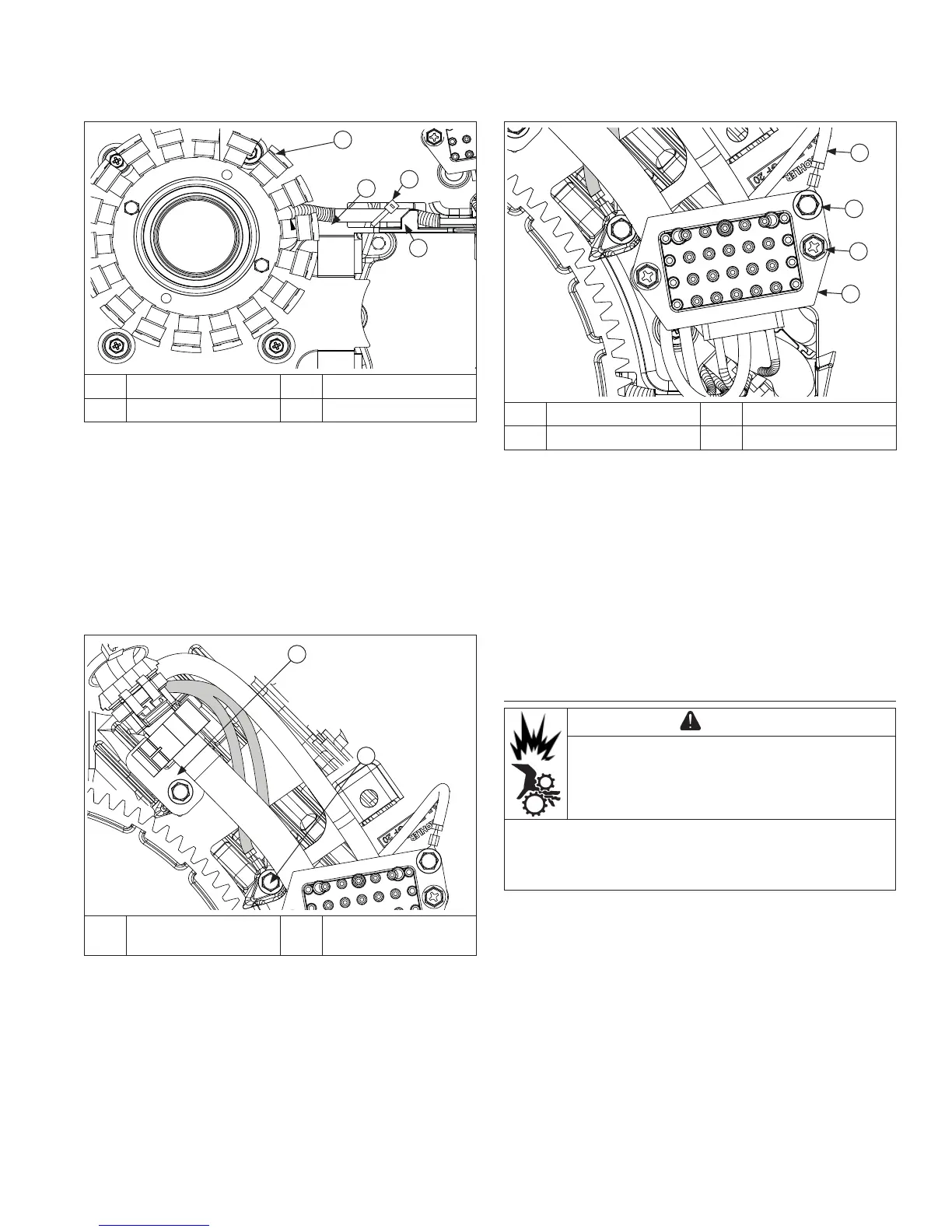
Install Rectifi er-Regulator
B
A
C
D
A Ground Lead B Ground Lead Screw
C Screw D Rectifi er-Regulator
1. If purple wire was removed, verify locking tang is
raised on terminal and push wire terminal into plug
prior to connecting to rectifi er-regulator.
2. Position rectifi er-regulator onto mounting posts and
secure with screws. Torque mounting screws to
2.5 N·m (22 in. lb.).
3. Engine has ground lead that secures in ground lug
fastener hole. Attach ground lead to rectifi er-
regulator and torque to 5.6 N·m (50 in. lb.) into new
holes, or 4.0 N·m (35 in. lb.) into used holes.
4. Connect plug to rectifi er-regulator.
Install Flywheel
CAUTION
Damaging Crankshaft and Flywheel Can
cause personal injury.
Using improper procedures can lead to broken
fragments. Broken fragments could be thrown from
engine. Always observe and use precautions and
procedures when installing fl ywheel.
NOTE: Before installing fl ywheel make sure crankshaft
taper and fl ywheel hub are clean, dry, and
completely free of any lubricants. Presence of
lubricants can cause fl ywheel to be over
stressed and damaged when screw is torqued to
specifi cations.
NOTE: Make sure fl ywheel key is installed properly in
keyway. Flywheel can become cracked or
damaged if key is not properly installed.
1. Install woodruff key into crankshaft keyway. Make
sure key is properly seated and parallel with shaft
taper.
2. Install fl ywheel onto crankshaft, being careful not to
shift woodruff key.
Install Stator
B
A
C
D
A Stator B Stator Leads
C Tie Strap D Molded Clips
1. Apply pipe sealant with Tefl on
®
(Loctite
®
PST
®
592™
Thread Sealant or equivalent) to stator mounting
holes.
2. Position stator, aligning mounting holes so leads are
at 3 o'clock position and toward rectifi er-regulator
mount on cylinder 1 side.
3. Install and torque screws to 9.3 N·m (82 in. lb.).
4. Route stator wires under molded clips and install
new tie strap.
Install Wiring Harness
A
B
A
Wire Harness
Clamp
B Ground Eyelets
1. Install wire harness under molded clips in backing
shroud assembly.
2. Install wire harness clamp and wire harness ground
eyelets. Torque M6 screws to 2.5 N·m (22 in. lb.) into
new holes, or 2.0 N·m (18 in. lb.) into used holes.