15124 690 01 Rev. S KohlerEngines.com
Electrical System
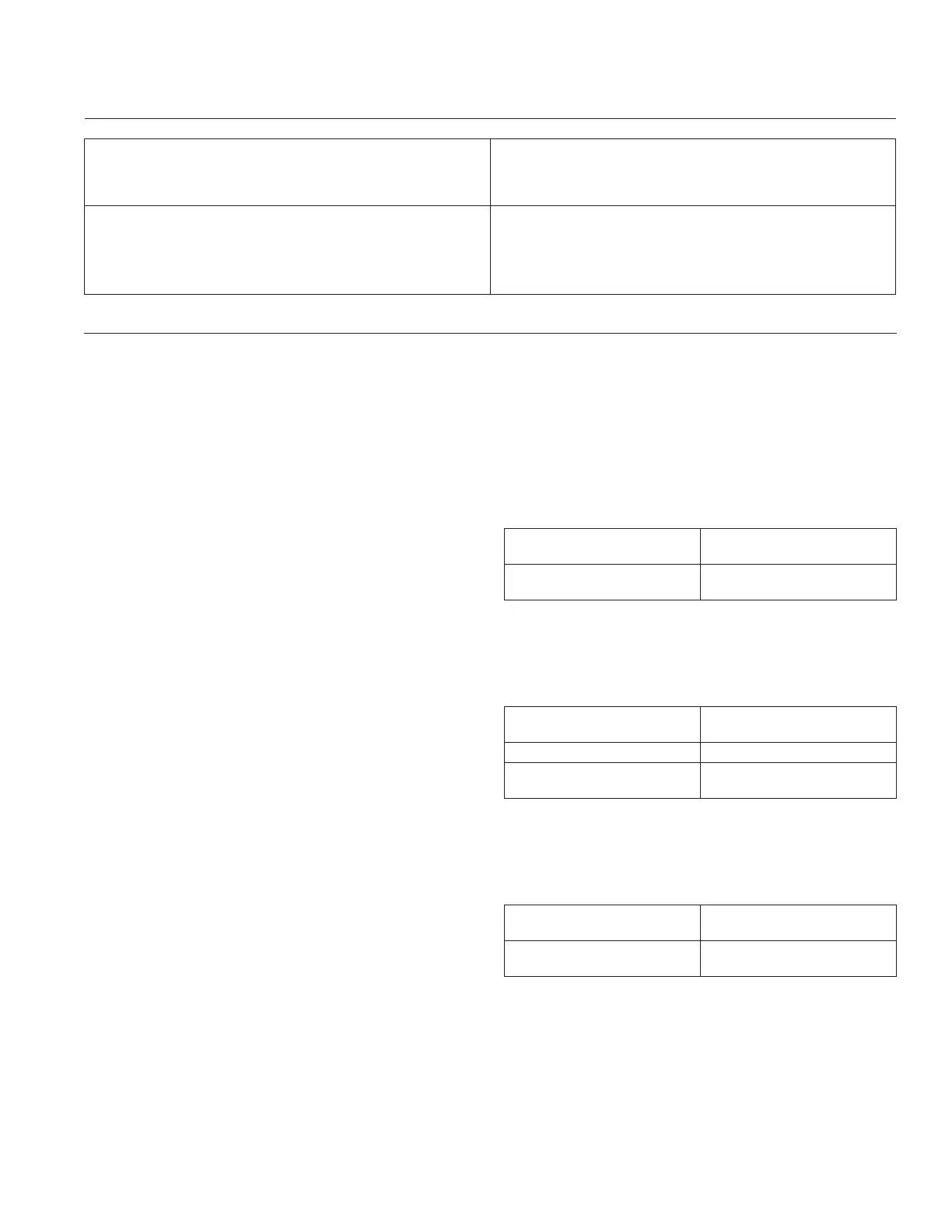
Condition Conclusion
20/25 amp
OK (green) light comes on and stays steady. Disconnect tester black lead attached to 1 AC terminal
and reconnect it to other AC terminal. Repeat test. If OK
(green) light comes on again, part is good and may be
used.
NOTE: A fl ashing LOW light can also occur as a result of
an inadequate ground lead connection. Make
certain connection location is clean and clamp is
secure.
Other lights come on.
Rectifi er-regulator is faulty and should not be used.
Troubleshooting Guide
20/25 Amp Battery Charging System
NOTE: Always zero digital volt-ohm meter (DVOM) on each scale before testing to ensure accurate readings. Voltage
test should be made with engine running at specifi c test condition noted. Battery should be checked for state
of charge (non-operating voltage 12.5 VDC or lower, battery should be charged or replaced).
When problems occur in keeping a battery fully charged or a battery charges at a high rate, battery or charging
system may be at fault. Before performing any testing, battery must be fully charged.
To test charging system:
1. Inspect charging system fuse. If damaged, replace
before continuing.
2. Visually inspect system components and wiring.
Look for damaged or loose wire connections,
including battery cables.
3. Set DVOM to DC volts, place red (positive) lead of
tester on rectifi er-regulator body and black
(negative) lead to battery negative (-) terminal. Run
engine and observe volt reading on meter. If voltage
is 0.5 VDC or less, continue with testing. If voltage is
higher than 0.5 VDC, inspect and repair wiring/
connections as needed (insuffi cient ground).
4. Perform these output tests for charging system using
DVOM set to DC volts.
a. With engine off and key switch in OFF position,
measure voltage at battery. If less than 12.4 VDC,
recharge battery and retest. If 12.5 VDC continue
with tests.
b. Run engine at high speed no electrical or
mechanical load (greater than 3000 RPM). After
running 1 minute, measure voltage at battery.
i. If voltage increases to between 13-15 VDC,
system is working correctly.
ii. If voltage increases to 15.5 VDC or higher,
system is overcharging. Replace rectifi er-
regulator.
iii. If voltage stays at 12.5 VDC or decreases,
charging system is NOT operating, proceed to
step 5.
5. With engine off , unplug rectifi er-regulator connector
and inspect connector terminals within connector
body and rectifi er-regulator terminals for corrosion/
arcing/damage. Repair/replace as needed. If OK,
proceed to next test.
6. Set DVOM to AC volts, place test leads to each
white stator wire. Run engine at 1200 RPM or
greater and monitor voltage.
Condition Conclusion
Voltage is 13 volts AC or
more.
Stator is OK.
Voltage is less than 13
volts AC.
Stator is faulty. Continue
with steps 7 and 8).
7. With engine off and stator unplugged from rectifi er-
regulator, check for resistance/continuity between
across stator leads (white wires).
Condition Conclusion
Resistance is 0.1/0.2
ohms.
Stator coil is OK.
Resistance is 0 ohms. Stator is shorted; replace.
Resistance is infi nity
ohms/no continuity.
Stator is open; replace.
8. With engine off and stator unplugged from rectifi er-
regulator, check for resistance/continuity from stator
leads (white wires) to ground.
Condition Conclusion
Resistance is infi nity ohms
(no continuity).
Stator is OK (not shorted
to ground).
Resistance (or continuity)
measured.
Stator leads are shorted to
ground; replace.
9. If stator tests good (steps 5-8), but system was
identifi ed in step 3 as not working, failure is likely
with rectifi er-regulator. Replace rectifi er-regulator,
retest system to confi rm repairs (step 4).
 Loading...