68
Reassembly
KohlerEngines.com 16 690 01 Rev. --
Install Ignition Modules
1. Rotate fl ywheel to position magnet away from
ignition module bosses.
2. CDI modules are installed with spark plug lead wire
from module always away from cylinder. On cylinder
1, single kill tab should be towards you. On cylinder
2, single kill tab should be away from you (in).
MDI modules are installed with fl at side out/towards
you.
3. Install each ignition module to crankcase bosses.
Slide modules up as far away from fl ywheel as
possible and snug screws to hold them in position.
4. Rotate fl ywheel to position magnet directly under 1
ignition module.
5. Insert a 0.25 mm (0.009 in.) fl at feeler gauge
between magnet and ignition module. Loosen
screws enough to allow magnet to pull module down
against feeler gauge.
6. Torque screws to 4.0-6.2 N·m (35-55 in. lb.).
7. Repeat steps 4 through 6 for other ignition module.
8. Rotate fl ywheel back and forth checking for
clearance between magnet and ignition modules.
Make sure magnet does not strike modules. Check
gap with a feeler gauge and readjust if necessary.
Final air gap 0.203/0.305 mm (0.008/0.012 in.).
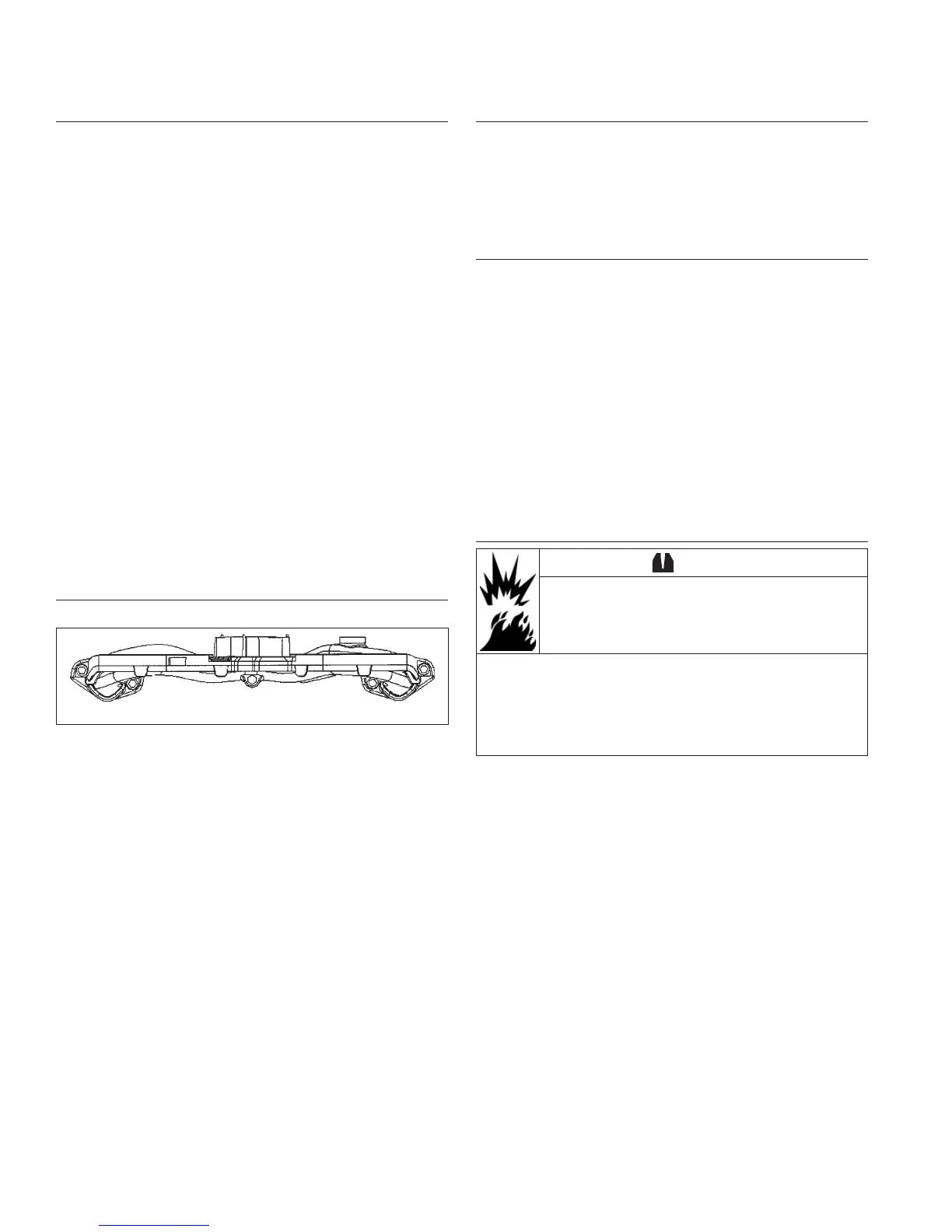
Install Intake Manifold
Torque Sequence
1
2
3
4
1. Install intake manifold using new O-rings, with wiring
harness attached, onto cylinder heads. Slide any
wiring harness clips onto appropriate bolts before
installing. Using sequence shown, torque screws in
2 increments, fi rst to 7.4 N·m (66 in. lb.), then to
9.9 N·m (88 in. lb.).
2. Connect kill lead to tab terminal on standard ignition
modules.
Install Rectifi er-Regulator (if equipped)
1. Install B+ terminal/lead into center position of
rectifi er-regulator plug so it locks in place, and
connect plug to rectifi er-regulator.
2. Attach rectifi er-regulator to opening in backing plate
from underside, and secure with mounting screws.
Torque screws to 4.0 N·m (35 in. lb.).
Install Inner and Outer Cylinder Baffl es
1. Attach outer cylinder baffl es and secure with M6
screw (lower cylinder location), and M5 screw into
backing plate. Tighten screws as listed following step
2.
2. Attach inner baffl es including any lifting straps to
cylinder head fl anges and to 2 crankcase mounting
bosses. Lift strap should be outside outer baffl e.
Secure with M5 screws. Remaining lower inner
baffl e mounting screws will be installed later.
Torque baffl e mounting screws:
M5 screws: 6.2 N·m (75 in. lb.) into a new cored
hole, or 4.0 N·m (35 in. lb.) into a used hole.
M6 screws: 10.7 N·m (95 in. lb.) into a new cored
hole, or 7.3 N·m (65 in. lb.) into a used hole.
Install Carburetor
WARNING
Explosive Fuel can cause fi res and severe
burns.
Do not fi ll fuel tank while engine is hot or
running.
Gasoline is extremely fl ammable and its vapors can
explode if ignited. Store gasoline only in approved
containers, in well ventilated, unoccupied buildings,
away from sparks or fl ames. Spilled fuel could ignite
if it comes in contact with hot parts or sparks from
ignition. Never use gasoline as a cleaning agent.
1. Install a new carburetor gasket. Make sure all holes
align and are open.
2. Install carburetor, throttle linkage and governor lever
as an assembly.
3. If carburetor is equipped with a fuel solenoid,
connect red (power) lead. Attach eyelet terminal of
ground lead to inner top carburetor cover mounting
screw.
 Loading...