5.8
Section 5
Fuel System and Governor
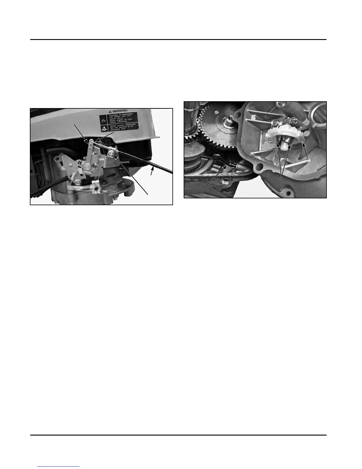
Figure 5-17. Bowden Cable Connection.
Governor
These engines are equipped with a centrifugal
Ě¢ǰȱȱǰȱȱȱȱ
the engine speed constant under changing load
ǯȱȱȱȦĚ¢ȱȱ
ȱȱȱȱȱȱȱȱǰȱȱȱ
ȱěȱȱȱȱȱĞǯȱȱȱȱśȬŗŞǯ
Figure 5-18. Governor Assembly.
Governor
Gear
Governor Shaft
Flyweights
Install Throttle/Choke Control Cable
ȱȱȱȱȱȱȱĴȦȱ
ȱǯȱȱȱȱȱȱȱ
ȱĴȱȱȱǯ
Dual Throttle/Choke Control Installation
1. Loosen the cable clamp and insert the cable
ȱȱȱǯȱȱȱśȬŗŝǯȱ
ȱ Řǯȱ ȱȱȱȱȱȱȱȱ
ȱȱȬȱǯȱȱȱȱ
selection, refer to the operating instructions of
the equipment this engine powers. See Figure
śȬŗśǯ
ȱ řǯȱ ȱȱĴȱȱȱȱȱȱ
ȱȱȱȱȬȱǯȱ
DZȱ ȱȱȱȱȱ¢ȱȱȱ
Ĵȱȱ¢ȱȱȱȱ
ǯȱȱȱĴȱȱȱȱȱ
a designated CHOKE position, be sure to
ȱĜȱĴȱȱȱȱȱ
ȱǯȱȱȱȱȱȱȱ
be placed ON.
ȱ Śǯȱ ¢ȱȱȱȱȱȱȱȱ
ȱȱȱȬȱǯ
ȱ śǯȱ ȱȱȱȱȱȱȱĴȱȱ
ȱȱȱ¢ȱǯȱ
ȱ Ŝǯȱ ȱȱȱȱ¢ǯ
Operation
As the governor gear rotates, centrifugal force causes
ȱĚ¢ȱȱȱȱȱȱǯȱ
ȱȱĚ¢ȱǰȱ¢ȱȱȱȱȱ
to protrude out. The regulating pin contacts the tab
ȱȱȱĞǰȱȱȱĞȱȱǯȱȱ
ȱȱȱȱĞȱȱȱȱȱ
ȱȱǯȱȱȱȱȱȱȱ
ȱȱȱȱȱĞȱȱȱȱ
ȱȱȱĴȱȱȱȱǰȱȱ¢ȱ
ȱȱȱĞȱȱȱȱ
ȱȱĴȱǯ
ȱȱȱȱȱȱȱȱĴȱȱȱ
ȯȱȱȱȱę¡ȬȱȱǻȱǼȱȯȱȱȱ
ȱȱȱȯȱȱȱȱȬȱȱ
ȯȱȱȱȱȱȱȱȱȱĴȱ
plate open. When the engine is operating, and the
governor gear assembly is rotating, the force applied
¢ȱȱȱȱȱȱȱĞȱȱȱ
ȱȱĴȱǯȱȱȱȱ
tension and the force applied by the regulating pin are
in equilibrium during operation, holding the engine
speed constant. When load is applied, and the engine/
governor gear speed decreases, the governor spring
ȱȱȱȱȱȱȱȱĴȱ
plate wider. This allows more fuel into the engine,
ȱȱǯȱȱȱȱȱ¢ȱ
Cable Clamp
Control Arm
Sheath
Bowden Cable
 Loading...