2 — INSTALLATION AND WIRING
pg. 19
Return to TOC Curtis AC F2-A, F4-A, F6-A Motor Controllers – FOS 4.5 – April 2022
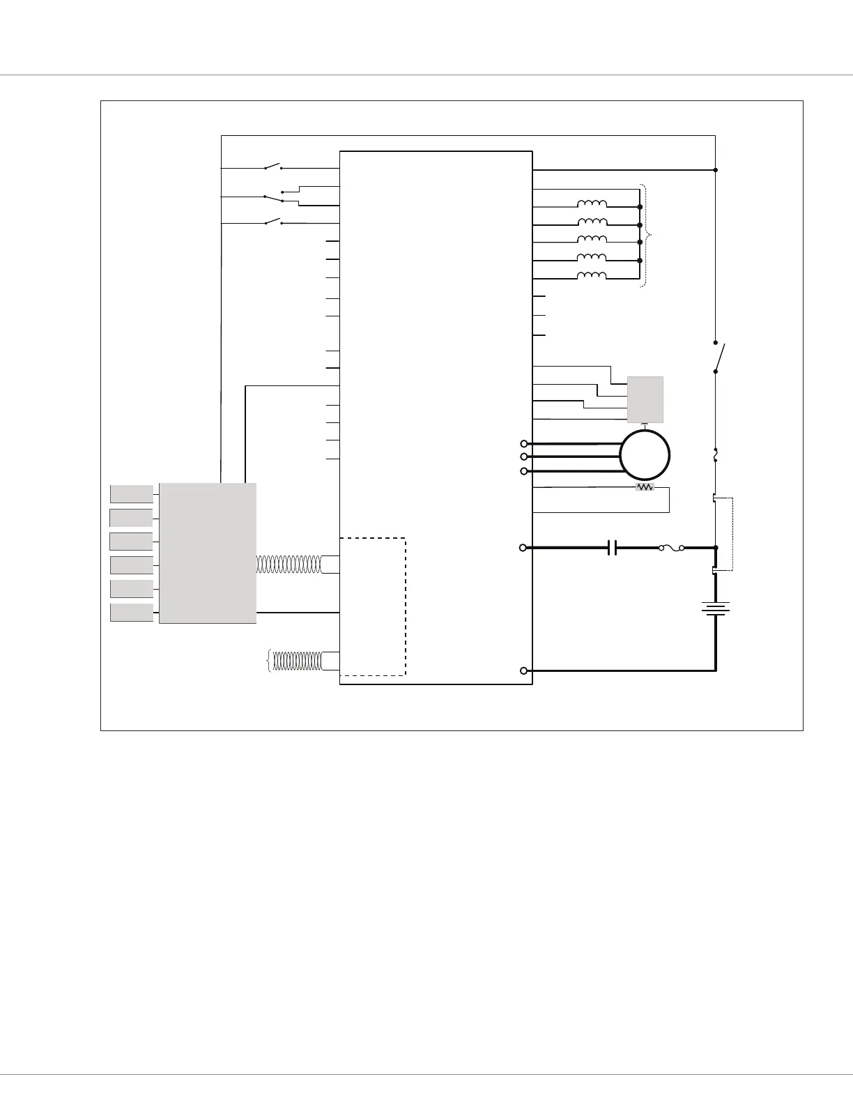
AC F4-A/F6-A CONTROLLER
Basic Wiring Diagram - CAN Tiller-Head / Isolated CAN
NO
NC
Emergency
Reverse
Interlock
Tiller-Head
Controller
Throttle
CAN 1
Power
Supply
Lower
Lift
Horn
Reverse
Forward
KSI
Input 8
Input 9
Input 7
AC
Induction
Motor
Input 31 / +5V
Input 3 / Enc 1A
Input 4 / Enc 1B
GND
Speed
Position
Sensor
Fuse
Coil Supply
Driver 4 / Input 24
Driver 3 / Input 23
Driver 5 / Input 25
Load-Hold Valve
Driver 6 / Input 26
Driver 7 / Input 27
Input 6 / Pot 6 Supply
Input 1 / Pot 1 Wiper
GND
Input 18 / Pot 18 Wiper
Input 19 / Pot 19 Supply
Driver 1 / Input 21
Driver 2 / Input 22
Proportional Valve
Input 13 / Enc 2B
Input 10
Input 11 / Enc 1C
Input 5
Input 12 / Enc 2A
Input 31 / +5V Ext Supply
(Not used)
Input 14 / +12V Ext Supply
CAN1 H
CAN1 L
CAN 2L
CAN 2H
Driver 8
Main Contactor
5V
A/Sin
B/Cos
GND
7
Travel
Limit
7
Keyswitch
Horn
Main Coil
18
EM Brake
26
31
32
8
16
22
26
9
13
23
35
28
29
4
3
2
5
6
19
2027
33
24
14
30
10
11
12
25
17
15
1
-
+
Safety Disabled
and
Reverse Polarity
Protected
Loads
34
21
CAN PORT #2
Fuse
twisted pair, recommended
EMERGENCY
STOP
E Stop
Pole A
E Stop
Pole B
Battery
B+
B–
U
V
W
GND
Input 2 / Motor Temp
Motor Temp
Sensor
+
−
twisted pair, recommended
Isolated GND
ISOLATED
CAN PORTS
Figure 15
AC F4-A, F6-A Isolated CAN. Tiller Head Wiring Diagram
 Loading...


