IGNITION TIMING-K482, K532 ENGINES
On K482 and
K532
engines, the breaker point assembly
is
mounted on the governor.
The breaker
rod rides on a cam on the governor drive shaft.
The governor is therefore timed to the engine and
must be
retimed if it has been removed for any reason
(see
Governor Instructions in Section
5).
The
governor also incorporates an automatic spark advance
-
retard mechanism.
Retard is
8' BTDC while
the advance point is 27' BTDC.
The advance spark point is marked
"SP" on the flywheel of the engine.
Use
the following procedure to adjust breaker point gap:
1. Remove breaker point cover.
2.
Turn engine over until breaker points are full open
--
measure gap with feeler gauge.
Maxi
-
mum opening should be ,020
"
. Adjust by loosening gap adjusting screw then insert screw
-
driver blade in adjusting notch to shift movable plate until ,020" maximum opening is
attained. Retighten gap adjusting screw and replace breaker point cover after initial
adjustment.
3.
Follow up with the final or precision adjustment using a timing light.
Final adjustment
is made
by shifting position of governor
--
refer to procedure below.
Several different types of timing lights are available
--
follow the manufacturer's instructions for
the particular type of timing light used. The following procedure can he used
with* timing lights.
Rotating the governor advances or retards the timing depending on which way the unit is turned.
1.
If boot type lead is used, remove hoot at
#l
cylinder (nearest flywheel) then wrap one end
of a short piece of fine wire around spark plug terminal.
Reconnect boot to terminal
so
that free end of the wire can protrude under the boot.
(Step 1 applies to timing lights hav
-
ing alligator clips.
)
2.
Connect one of the timing light leads to the wire protruding from under the boot.
3.
Connect second timing light lead to hot (ungrounded) side of battery
-
-
see timing light
instructions for proper
ba;tery size, wir- connections, etc.
4.
Connect third timing light lead to common ground.
5.
Before starting, rotate engine until '-5P" mark is observed in timing sight hole
--
chalk
marK the line for easy reading.
6.
Start engine and operate at 1200
RPM
or
above.
Aim timing light into sight hole
--
light
should flash just as
"SP" mark is centered in sight hole.
If light flashes before mark is
centered, timing is
overadvanced.
If light flashes after mark is centered, timing is
retarded.
7.
To adjust, loosen (do not remove) governor flange mounting capscrews and shift or rotate
until timing mark is exactly centered as light flashes.
Retighten flange mounting screws
after exact timing is achieved.
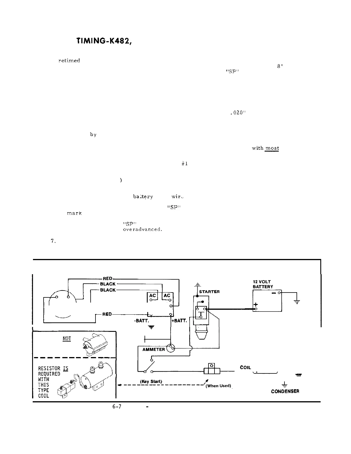
REGULATOR
FLYWHEEL
REG.
ALTERNATOR
-0ATT. +BATT.
-
-
REG.
RESISTOR
REQUIRED
$J
WITH
@
1
THIS
COIL
-----------
LIGHTS
SWITCH RESISTOR
SPARK SPARK
PLUG
BREAKER
POINTS
COIL
-
=
*
CONDENSER
I
I
I
FIGURE
6-7
--
K482
-
30 AMP ALTERNATOR SYSTEM, WIRING DIAGRAM
6.8