TP-7070 7/18108 Section 5 Accessories
5.3 Input and Output Modules
The following factory-installed modules are available as
optional accessories.
D Analog Input/Output Module
D Digital I/O Module
D Thermocouple Input Module
The modules are factory-installed in the customer
connection box. Module power and CAN Bus
communications with the controller are factory
connected. The communication speed and module
CAN addresses are factory set. Do not change the
speed or CAN address DIP switch settings.
The modules are equipped with two diagnostic LEDs
that can be used for troubleshooting. See Figure 5-5.
5.3.1 Analog Input/Output Module
The Analog Input/Output (I/O) Module provides two
output connections and four input connections. See
Figure 5-3 for I/O specifications and Figure 5-4 for
connections.
The factory default input and output settings are
undefined. I/O settings can be loaded by an authorized
service technician. Contact your Kohler distributor with
your requirements for inputs and outputs.
Input/Output Specifications Connection
Input
0--20mAmps
Impedance 100 ohms
0.75 to 1.5 mm
2
Output
0--20mAmps
100 -- 600 ohms
0.75 to 1.5 mm
2
Figure 5-3 Analog Input/Output Specifications
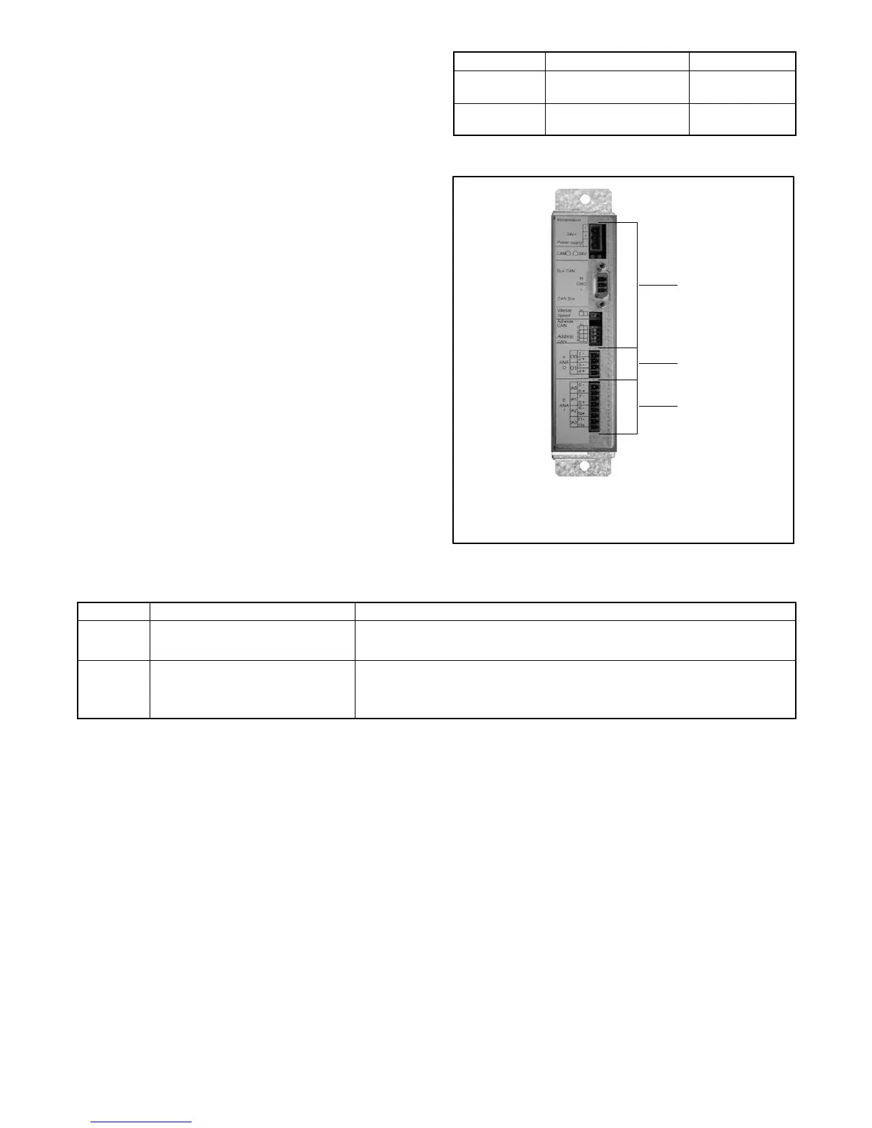
1
2
3
31613391201/301/401
1. Factory connections or settings
2. Analog output connections 0 and 1
3. Analog input connections 0 -- 3
Figure 5-4 Analog Input/Output Module
LED Description LED Operation
1 Power LED Green: The module is correctly powered.
Off: Module is not powered.
2 Can bus 1 Communication LED Flashing green: CAN communication is consistent.
Steady green: No CAN communication.
Off: No CAN c ommunication.
Figure 5-5 Module Diagnostic LEDs