TP-7070 7/18110 Section 5 Accessories
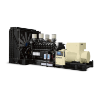
5.3.3 Thermocouple Input Module
Up to three thermocouples can be connected to the
Thermocouple Module. Type K or PT100
thermocouples can be connected. See Figure 5-9 for
thermocouple specifications. See Figure 5-11 and
Figure 5-12 for connections.
Medium voltage (larger than 600 volts) units are
equipped with two thermocouple modules with the
settings shown in Figure 5-10.
Temperature data can be viewed using the Custom View
button on the controller. See Section 2.7.5. If no
thermocouple modules are installed, all temperatures
will display 32_F(0_C). If nothing is connected to a
channel on a thermocouple module, --58_F(--50_C) is
displayed.
Thermocouple
Type
Temperature
Range
Connection
PT100
0 -- 200_C
(32 -- 392_F)
0.75 to 1.5 mm
2
K Thermocouple
--20 -- 1000_C
(--4 --1832_F)
0.75 to 1.5 mm
2
Figure 5-9 Thermocouple Types and Connections
Thermocouple Module 1 Thermocouple Module 2
Phase A Temp Front Bearing Temp
Phase B Temp Rear Bearing Temp
Phase C Temp User PT100 Temp
Figure 5-10 Thermocouple Module Default Settings
for Medium Voltage Generators
1
2
31613391201/301/401
1. Factory connections or settings
2. Thermocouple connections 0 -- 2, Type K or PT100
Figure 5-11 Thermocouple Module
24V
1
2
3
4
2
3
+
+
+
+
--
--
--
--
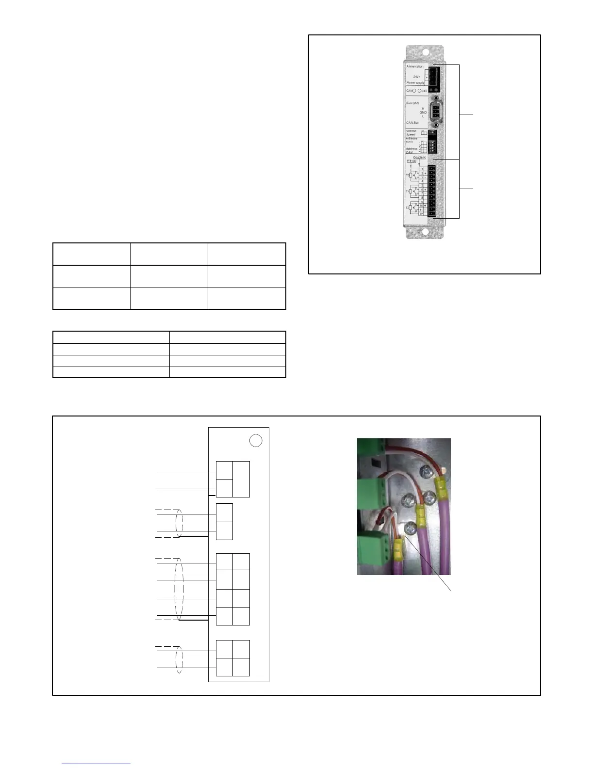
24VDC Power Supply
(9 -- 40 VDC)
31613391201
0--20mA
PT100
K
2XGround
Shielding Connection
Note: Cable shields must be grounded as shown.
Figure 5-12 Connections