63
ST_30
ST_30
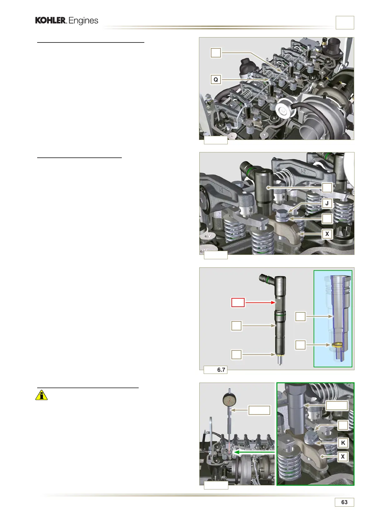
X
K
J
Fig. 6.6
Fig. 6.7
Fig. 6.8
Q
R
J
X
K
Z
BC
Z
S
S
V
Fig. 6.5
ED0053030410
INFORMATION FOR REPLACING THE FUNCTIONAL UNITS
6.1.5 Injection pump disassembly
Important
• Before proceeding with the disassembly, identify the pump
code from its identifying name plate (Pos. 12 - Tab. 2.12)
and remove the cylinder injector 1 (Par. 1.4 - 6.1.1 - 6.1.2 -
6.1.3 - 6.1.4).
• Alternatively, you can identify the pump from the online
spare parts catalogue (https://partners.lombardini.it/App/
SparepartCatalogue/Default/Catalogue.aspx).
1 -
Insert the tool ST_30 into the injector N°1 and fix it with the
fixing brace X, capscrew J and washer K.
NOTE: Do not tighten the capscrew J.
6.1.3 Fuel return pipes disassembly
1 - Undo the screws Q and remove hose R.
6.1.4 Injectors disassembly
1 - Undo the screw J and remove washer K and then bracket
X.
2 - Remove the injector Z.
NOTE: Should you be unable to remove the electronic injector
(acting only on point BC), use an open-ended spanner
(Ã 11 mm), by applying small rotations to unblock the
component.
3 -
Seal all injection component unions as illustrated in Par.
2.9.7.
4 -
Ensure that gasket S has remained in the correct position
(Fig. 6.7). Otherwise, recover the gasket from inside the
electronic injector V manifold.

 Loading...


