65
G1
F1
E1
E1
ST_13
J1
P1
D1
ST_13
D1
D1
C1
Fig. 6.13
Fig. 6.14
Fig. 6.15
J2N1
K2
K1
L1
M1
Fig. 6.12
ED0053030410
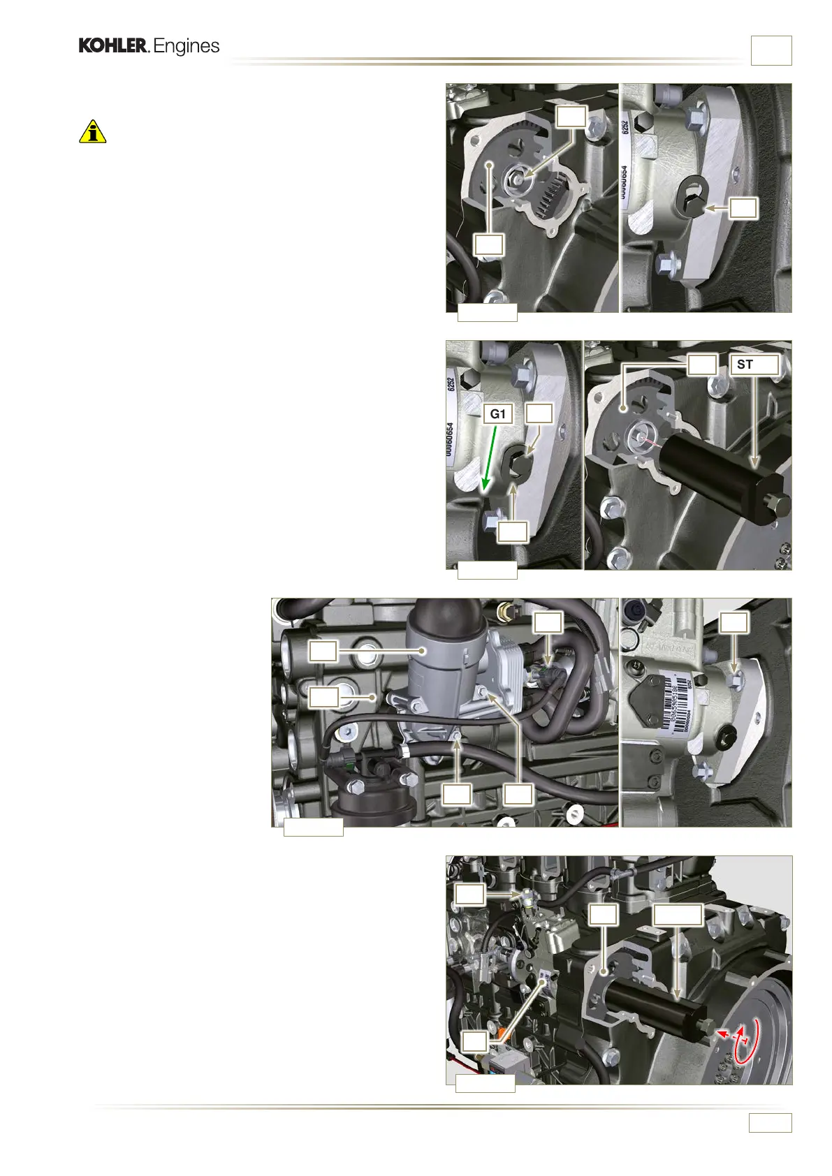
INFORMATION FOR REPLACING THE FUNCTIONAL UNITS
11 - Undo the capscrew E1 and shift the slotted plate F1 in the
direction of arrow G1.
12 - Tighten screw E1 to block the pump (tightening torque to
12 Nm).
13 -
Screw the tool ST_13 on the gear D1.
18 -
Undo the screw P1.
19 - Tighten the screw of tool ST_13 to disconnect the injection
pump J1 from the high pressure pump control gear D1.
20 - Undo the screws J2 and extract the injection pump J1.
21 - DO NOT remove the tool ST_13.
10 - Undo and remove the nut C1 fixing the injection pump
control gear D1.
Important
• After removing the nut C1, ensure that the correct advance
value has remained unchanged on ST_30.
• Be careful that the nut C1 does not fall into the timing cover.
14 -
Perform the operations of
point 1 of Par. 5.2.
15 -
Remove quick fitting N1.
16 - Loosen capscrews K1 and
K2 and detach Oil Cooler
unit L1 from crankcase
M1.
17 - Loosen the screws J2.

 Loading...


