66
Fig. 6.16
J1
J2
Q1
M1
G2
E1
F1
E1
Fig. 6.17
M1
Fig. 6.18
D1 S1
C1
Fig. 6.19
R1
R2
K1
K2
L1
ED0053030410
INFORMATION FOR REPLACING THE FUNCTIONAL UNITS
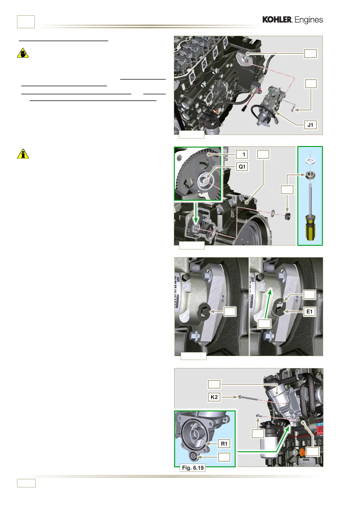
6.1.6 Injection pump assembly
Important
• Before assembling the new pump J1, make sure that plate
F1 can move freely and that fastening capscrews E1 are not
loose (the pump sold as a spare part is supplied with the
cylinder injection timing blocked N° 1).
• Ensure that the coupling surfaces on shaft Q1 and gear
D1 are free from impurities and lubrication residues.
• Remove the guard cap only when the pipes are reconnected.
• Do not remove the tool ST_30.
1 - Mount the injection pump J1, inserting the shaft Q1 in the
gear D1.
Important
• Always change screws J2 with new ones or apply Loctite
2701 to the threads.
2 - Clamp the screws J2 on the crankcase M1 (tightening
torque at 25 Nm).
3 - Remove the tool ST_13.
4 - Ensure that the correct advance value has remained
unchanged, tighten nut C1 on shaft Q1 (as shown in Fig.
6.17, you are allowed to use a screwdriver to guide nut C1
onto shaft Q1 in order to prevent it from accidentally falling
inside carter S1 - tightening torque at 140 Nm).
5 - Undo the capscrew E1 and shift the slotted plate F1 in the
direction of arrow G2.
6 - Tighten screw E1 (tightening torque to 5.5 Nm).
The injection pump is unlocked.
7 - Remove the tool ST_30 and ST_34.
8 -
Assemble Oil Cooler L1 onto crankcase M1 by means of
capscrews K1 and K2.
NOTE: Always replace the gasket R1, R2 at each assembly.
 Loading...


