67
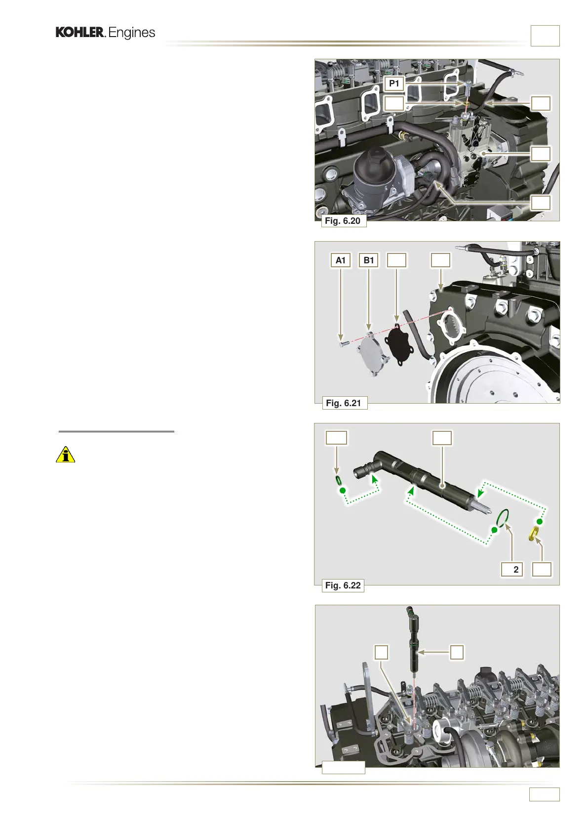
Fig. 6.20
Fig. 6.21
N1
P1
T1 U1
J1
A1 B1 V1 S1
Fig. 6.22
Z
W1
W2
Z
V
Fig. 6.23
S
ED0053030410
INFORMATION FOR REPLACING THE FUNCTIONAL UNITS
6.1.7 Injector assembly
Important
• To prevent damaging the injection system, the protection caps
(Par. 2.9.7) must be removed during assembly.
1 - Lubricate the gaskets W1, W2, S, and fit them on the
injector Z.
2 -
Fit the injector Z in the sleeve V.
9 -
Secure tube U1 by means of capscrew P1, inserting
gasket T1.
10 -
Fit quick coupling N1 onto pump J1.
11 -
Secure plate B1 by means of capscrews A1, inserting
gasket V1 onto carter S1 (tightening torque at 10 Nm).

 Loading...


