69
Y1
E2
H6
A
B
H
F
G
C
D2
E
P
Z1
M
M1
M2
L
B2
A2
N
D
E
C2 A2
ST_17 ST_17
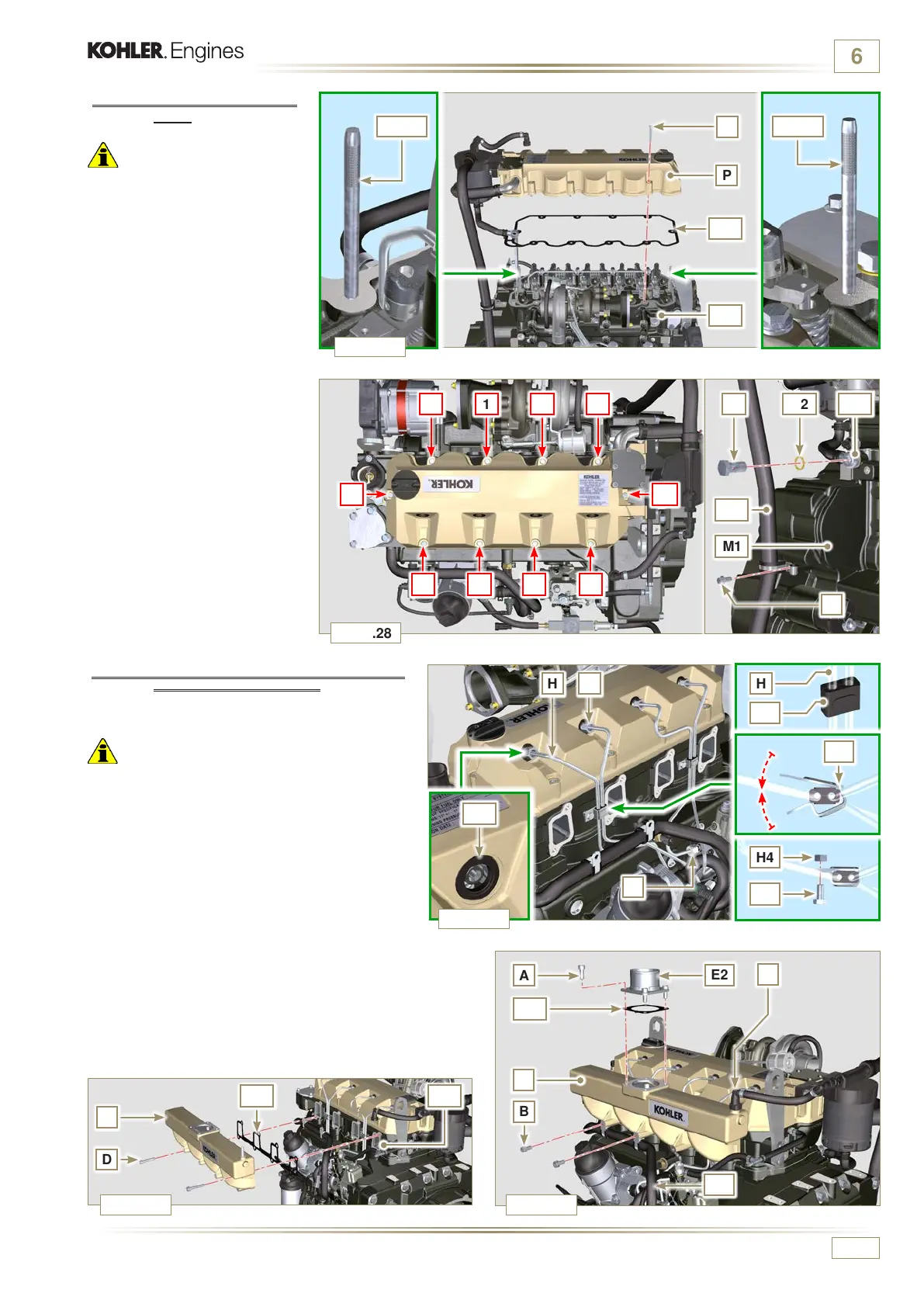
Fig. 6.28
Fig. 6.29
Fig. 6.27
Fig. 6.30 Fig. 6.31
1 3 75
8
9
4 2 6
10
H
H3
H4
H5
H2
M3
ED0053030410
INFORMATION FOR REPLACING THE FUNCTIONAL UNITS
6.1.10 Installation of the fuel injector pipes
(pump injector/injectors)
1 -
Position pipes H on the injectors and on the
injector pump.
Important
• Tighten the nuts F and G manually, without
clamping them.
2 - Tighten
the nuts F and G
(tightening torque at 25
Nm).
3 - Secure tubes H by means of clamps H2,
assembling:
- H3 rubber element;
- clamp H2 on element H3;
- secure clamp H2 by means of capscrew H4
and nut H5 (tightening torque at 10 Nm).
4 -
Secure manifold E onto cylinder head A2 by
means of capscrews D, inserting gasket C2.
5 -
Secure suction line E2 onto manifold E by means of
capscrews A, inserting gasket D2.
6 -
Fit quick coupling C onto manifold E.
7 -
Fasten the pipe H6 on the manifold E with the screws B.
6.1.9 Assembly Rocker arm
cover
Important
• The gasket Z1 between the
rocker arm cover and the cylinder
head must always be replaced
every time it is disassembled.
1 - Position tool ST_17 onto the
head in correspondence with
the two fastening holes 9 and
10.
2 -
Position gasket Z1 and cap P
on cylinder head A2 matching
the holes of fastening
capscrews N with the aid of
the gudgeon guides ST_17.
3 -
Attach the rocker arm cover P
on the head A2 with the screw
N adhering to the tightening
sequence shown in Fig. 6.28
(tightening torque to 10 Nm).
4 -
Secure the hose M2 with the
screw L (tightening torque to
10 Nm).
5 -
Clamp the fitting M3 with the
screw M (tightening torque to
25 Nm) inserting the gasket
B2.

 Loading...


