9
137
_07
Fig. 9.27
A
Fig. 9.28
C
E
D
D
B
Fig. 9.30
1
14
15
16
17
18
19
20
2
24
23
22
21
10
11
12
13
9
8
7
6 5 4 3
Fig. 9.29
G
E
F
L
L
M
ST_18 ST_18
ED0053029590
ASSEMBLY INFORMATION
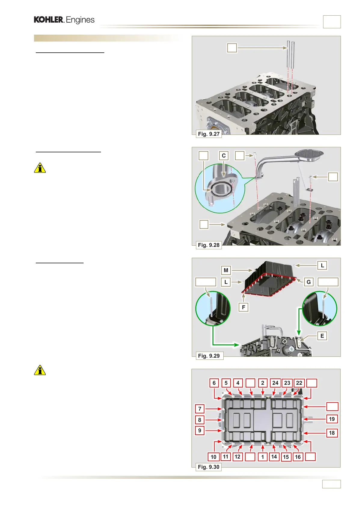
9.4.2 Oil suction pipe
Important
• It is mandatory to replace the gasket B after each assembly.
• Always replace capscrews D with new ones or alternatively
apply Loctite 2701.
1 - Insert the new gasket B in the seat of the oil suction hose
flange D.
2 - Secure the hose C on the crankcase E with the screws D
(tightening torque 10 Nm).
9.4 Oil sump unit assembly
9.4.1 Oil vapour pipes
1 - Apply Loctite 648 on the pipe threads A.
2 - Screw and tighten the pipes A (tightening torque of 15
Nm).
9.4.3 Oil Sump
1 - Ensure that the contact surfaces F of the oil sump G and
the crankcase E are completely clean.
2 - Apply a bead of approx. 2.5 mm of sealant (Loctite 5660)
on the surface F of the oil sump G.
3 - Position the oil sump G on the crankcase E in line with the
fastening holes (use the aid of tool ST_18).
Important
• Tighten the screws L, strictly following the sequence and
tightening torque indicated.
4 - Tighten the screws L following the sequence indicated
(tightening torque 25 Nm).
5 - After tightening all of the screws, loosen screw n°1 and re-
tighten it to the torque value specified in step 4.
6 - Check that the oil drain plugs M are tight (tightening torque
35 Nm).

 Loading...


