172
11
_07
Fig. 11.16
Fig. 11.17
Fig. 11.19
NP
L
N
F
N
B
C
A
F
E
E
G
H
D
R
Q
M
A
X
S
F
Fig. 11.18
ED0053029590
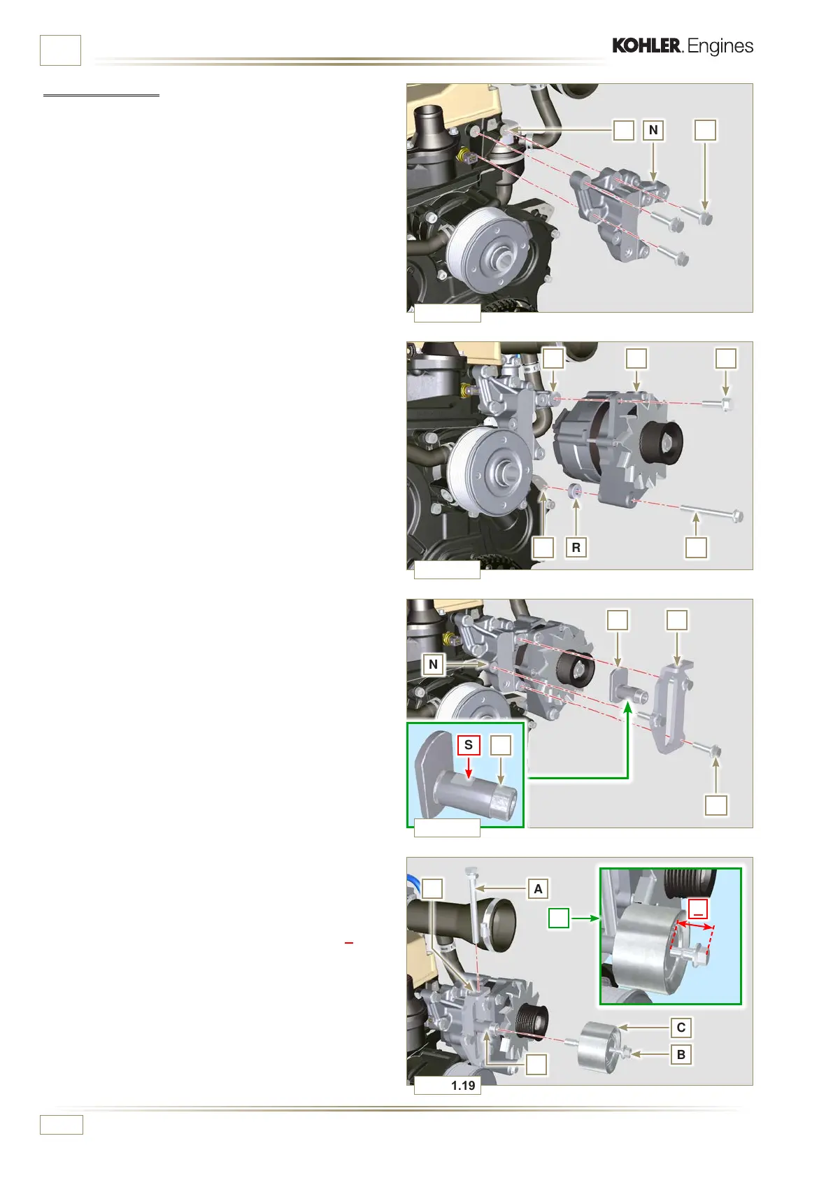
INFORMATION ABOUT OPTIONAL COMPONENTS
11.4.2 Assembly
1 - Secure the bracket N using the screws M on the cylinder
head P (tightening torque at 25 Nm).
2
- Insert the screw H into the fixing hole on the alternator L.
3 - Insert the spacer R on the screw H (between the alternator
and crankcase).
4 - Tighten the screw manually H onto the crankcase Q.
5 - Orientate the second fixing hole of the alternator L with
the hole of the bracket N, secure the alternator L using the
screw G (tightening torque at 25 Nm) onto the bracket N
and then the screw H (tightening torque at 25 Nm).
6
- Insert the pin F in the plate slot E.
7 - Orientate the pin F with the surface S (support for screw A)
upwards.
8 - Secure the plate E using the screws D on the bracket N
(tightening torque at 25 Nm).
9 - Insert the screw B in the tightening pulley C.
10
- Manually tighten the screw B onto the pin F up to the stop;
Undo the screw B again by one turn.
NOTE: The screw B must protrude by about 32 mm (A) from
the surface of the tightening pulley C (see detail X)
11 - Install the new belt H (Fig. 11.10).
12 - Tighten the screw A onto the plate E up to the stop on the
pin F.
13 - Perform the operations from point 6 to 8 of Par. 11.3.
 Loading...


