173
11
_07
Fig. 11.20
Fig. 11.21
Fig. 11.22
Fig. 11.23
A
CEB
F
B
J
D
H
G
G
L
A
B
ED0053029590
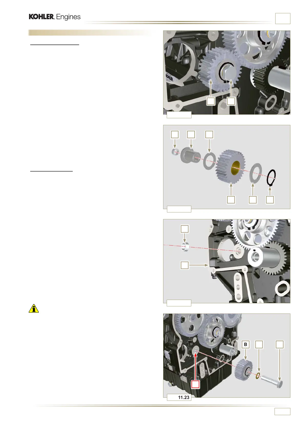
INFORMATION ABOUT OPTIONAL COMPONENTS
11.5 Idler gear (for 3
rd
/ 4
th
PTO)
11.5.1 Disassembly
1 - Undo the screw A and remove the gear unit B.
2 - Remove the retainer ring C from the seat of the pin D.
3 -
Remove the shoulder washer E, the gear B, the shoulder
ring F and the bushing G from the pin D.
11.5.2 Assembly
1 - Insert gudgeon D:
- shoulder ring F (minimum shim)
- gear B
- shoulder ring E
- retainer ring C.
2 - Insert the bushing G on the crankcase L.
Important
• Always replace the gasket H every time it is disassembled.
• Check that the perforated screw A is free from impurities
inside it.
• Lubricate the thread and under the head of the screw A with
Molyslip.
3 - Position the gear unit B on the hole J using the bushing G
to centre.
4 - Secure the gear unit B using the screw A inserting the
gasket H (tightening torque at 40 Nm).
5 -
Loosen and tighten the screw A again (tightening torque at
20 Nm + 20°).
 Loading...


