175
11
_07
Fig. 11.29
R
G H
D
E
F
F
Fig. 11.27
Fig. 11.28
P
D
E F F
Q
HG
F
J
KJ
D
Fig. 11.30
ED0053029590
INFORMATION ABOUT OPTIONAL COMPONENTS
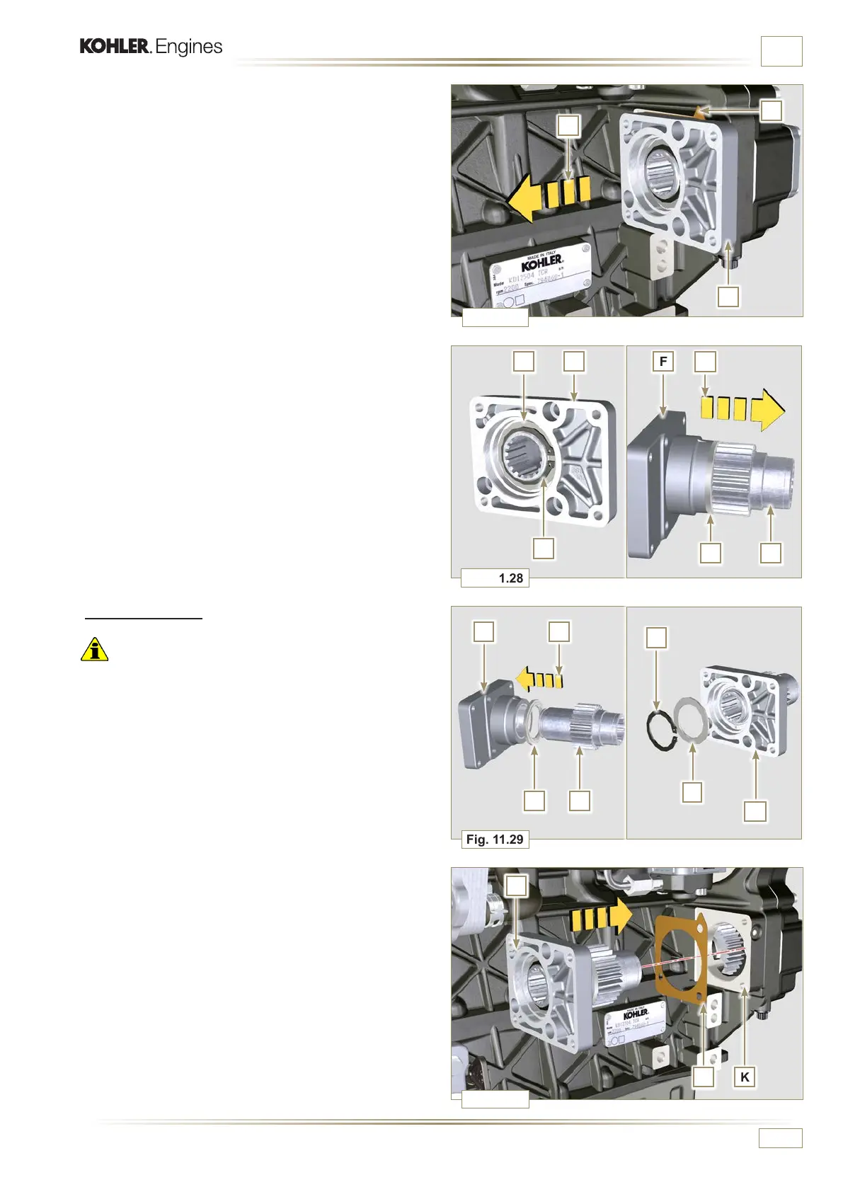
11.6.2 Assembly
Important
• Always replace the gasket J at each assembly.
• Lubricate the gear H with oil.
• Always change capscrews N with new ones or alternatively
apply Loctite 2701.
1 - Insert the gear H in the flange F in the direction of the
arrow R inserting the shoulder ring G.
2 - Insert the shoulder ring E on the flange F and clamp the
gear H using the retainer ring D.
3 - Position flange F on the crankcase K inserting the gasket
J, and insert gear H in crankcase K.
4 -
Remove the flange F with the components D, E, G and H in
the direction of the arrow P.
5 - Remove the gasket J.
6 - Remove the retainer ring D and the shoulder washer E.
7 - Remove the gear H and the shoulder ring G from the flange
F in the direction of the arrow Q.
 Loading...


