176
11
_07
Fig. 11.32
F
H
CB
A
A2
B
F H J
S
K
M
N R
A2
D
P
Q
C
N
Fig. 11.31
Fig. 11.33
F
ED0053029590
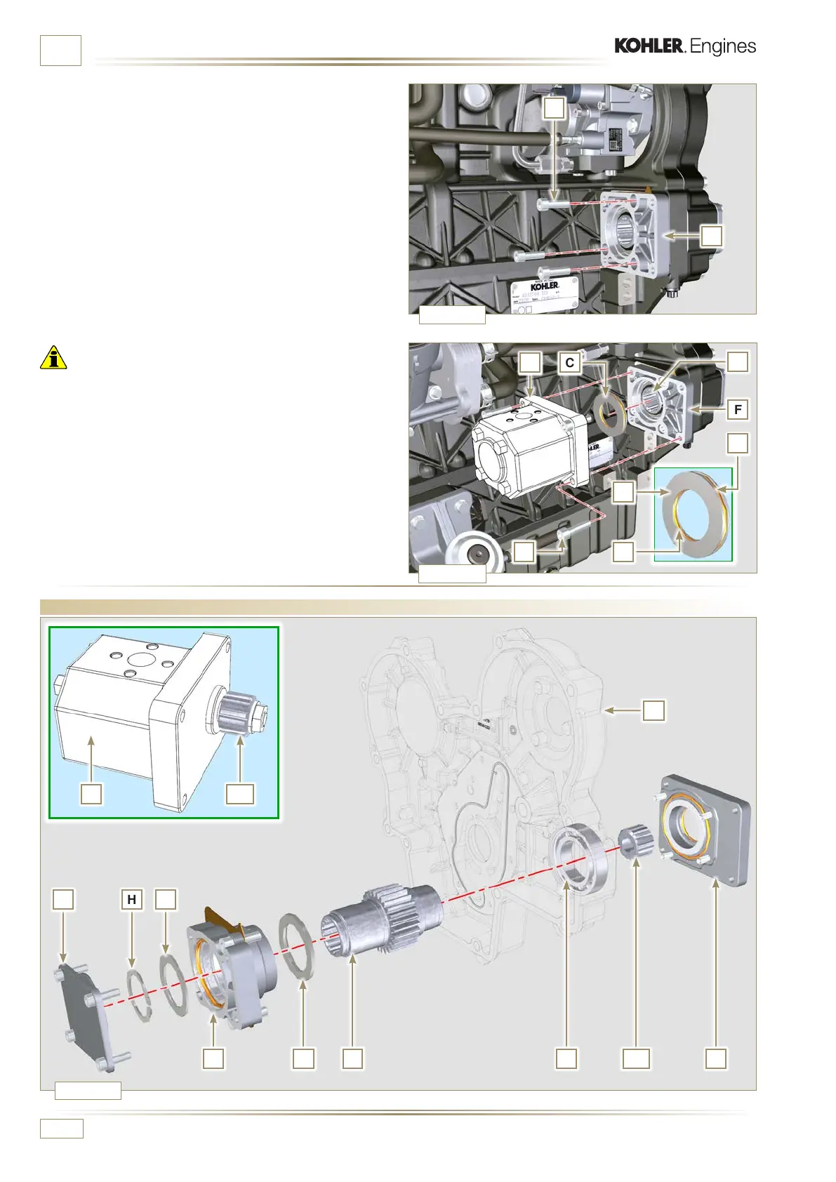
INFORMATION ABOUT OPTIONAL COMPONENTS
11.7 4
th
PTO (replacement)
4 -
Secure the flange F using the screws N (tightening torque
at 25 Nm).
Important
• Always replace the gaskets P and Q at each assembly.
5 - Insert the centring ring C in the flange F up to the stop.
6 - Position the pump B on the flange F engaging the gear H.
7 - Secure the pump B using the screws A on the flange F
(tightening torque at 25 Nm).
 Loading...


