179
11
_07
Fig. 11.43
Fig. 11.44
S
C
U B
D
A
Fig. 11.42
E F
K
F
V
T
D
ED0053029590
INFORMATION ABOUT OPTIONAL COMPONENTS
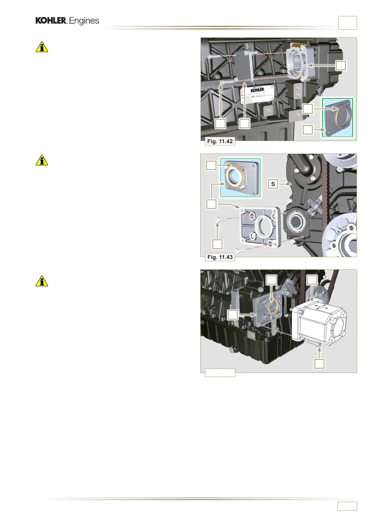
Important
• Always replace the gasket T after each assembly.
7 - Position and tighten flange D by means of capscrews C on
carter S (tightening torque 10 Nm - ST_06).
Important
• Always replace the gasket U after each assembly.
8 - Position the gasket U on the flange D.
9 - Secure the pump B using the screws A (tightening torque
at 25 Nm) on the flange D.
Important
• Always replace the gasket V after each assembly.
5 - Insert gasket V on cover F, insert and position the cover F
on flange K.
6 - Secure the cover F using the screws E on the flange K
(tightening torque at 25 Nm).
 Loading...


