6
81
_07
Fig. 6.40
N
H
L
Fig. 6.42
E
A Q
C
B
Fig. 6.41
PE
P
P
D
C
Fig. 6.43
A
P
ED0053029590
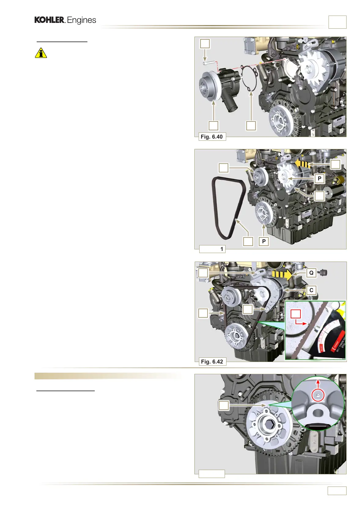
INFORMATION FOR REPLACING THE FUNCTIONAL UNITS
6.5.2 Assembly
Important
• Always replace the gaskets L, at each disassembly.
• Always replace the belt E after each assembly.
• If the engine is fitted with the Poly-V belt, perform the
operations described in Par. 11.3.
1 - Fit the pump N with the screws H interposing the new
gasket L (tightening torque at 25 Nm).
2 -
Reinsert the pipe G and hook the clamp F (Fig. 6.38).
3 - Rehook the clamp M on the pump N (Fig. 6.39).
4 - Push the alternator C in the direction of the arrow D.
5 - Insert the belt E on the pulleys P.
6 -
Pull the alternator C in the direction of the arrow Q.
7 - While tensioning the alternator C, first clamp screw A
(tightening torque at 25 Nm) and then screw B (tightening
torque at 69 Nm).
8 - Check the tension of the belt E with the instrument
(DENSO BTG-2), positioning it in point P (the tension must
be between 350 and 450 N).
9 - If the tension values do not correspond, tighten screws A
and B, then repeat operations 6, 7 and 8.
6.6 Target wheel replacement
6.6.1 Disassembly
1 - Position the crankshaft with the 1st cylinder in TDC,
reference A upwards.
2 - Remove the alternator belt following steps 1 and 2
(Par. 6.5.1).

 Loading...


