24 TT-1625 7/17
6.5 P37, 3-pin power connections. Each RSA III
requires a 12/24-volt, 200 mA (min.) DC power
source. The RSA III voltage should match the
generator set starting system. Provide an engine
starting battery connection to P37. The 12- or
24-volt positive and negative wires can be
connected to either P37-2 or P37-3 terminals as
they are not polarity sensitive. See Figure 20 for
location of P37 and Figure 37 for terminal
identification.
Attach to the battery positive (+) connection at the
starter solenoid and the battery negative (--)
connection at the engine ground. Do not use
terminals 42A and 2 on the controller connection
kit terminal strip. The battery positive (+) lead
should be fuse protected.
AC adapter kit GM62466-KP1 is available to
supply 12 VDC power to a single RSA III. See
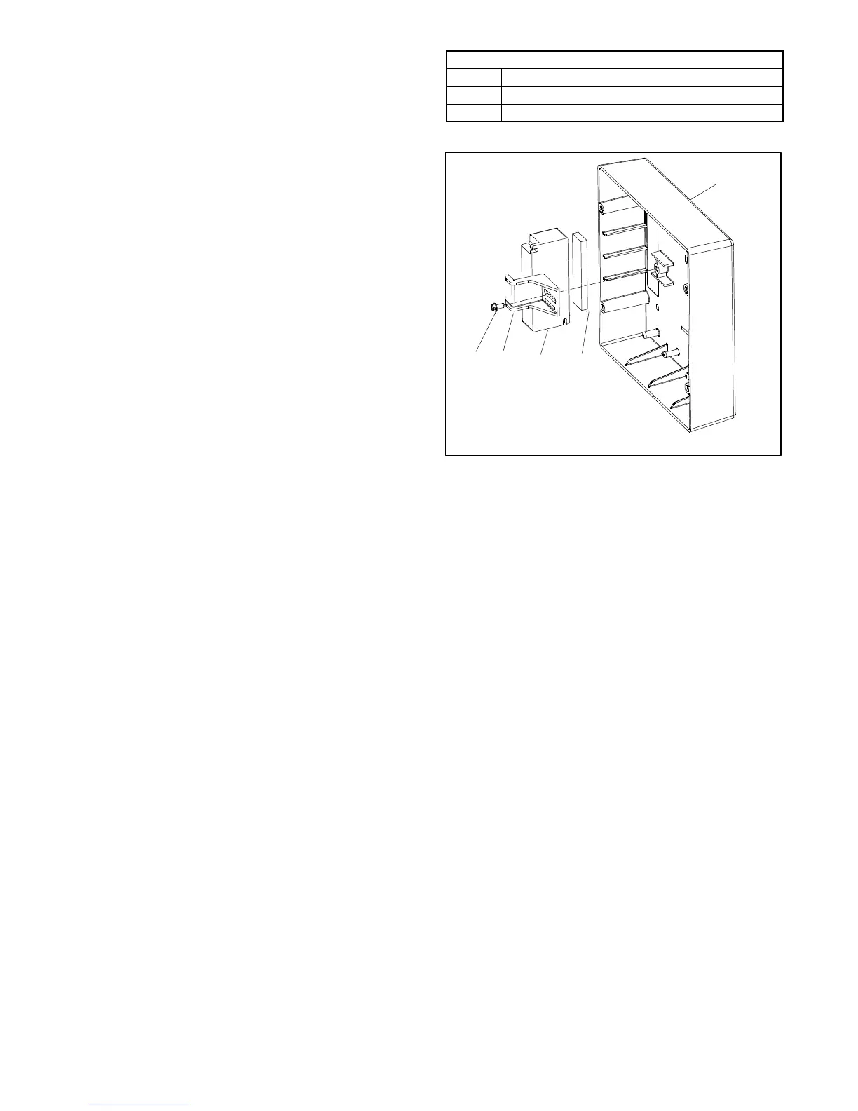
Figure 38 for components of the kit and Figure 62
for electrical connections to P38.
Note: Keep the power source deenergized at
this time.
P37 Power Connections
P37-1 Ground
P37-2 12/24 VDC battery input1 (not polarity sensitive)
P37-3 12/24 VDC battery input2 (not polarity sensitive)
Figure 37 P37 Power/CAN Connections
GM60399-A
1. RSA III box
2. Rubber gasket
3. Power supply GM60407
4. Clamp GM60404
5. Screw X-67-113
6. Terminal block GM20930 (not shown)
1
32
45
Figure 38 AC Adapter Kit G M62466-KP1
 Loading...