Section 6
Generator
6-1. GENERAL
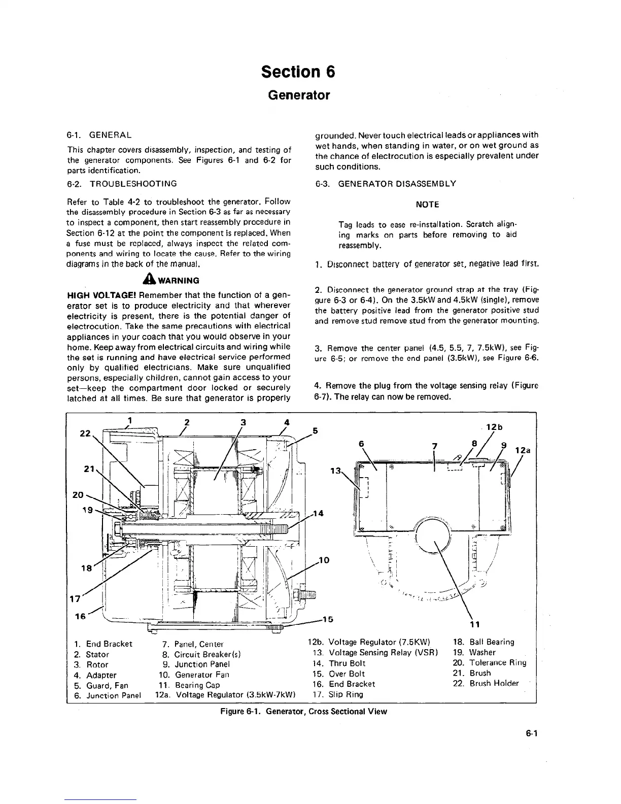
This chapter covers disassembly, inspection, and testing of
the generator components. See Figures 6-l and 6-2 for
parts identification.
grounded. Never touch electrical leadi or appliances with
wet hands, when standing in water, or on wet ground as
the chance of electrocution is especially prevalent under
such conditions.
6-2. TROUBLESHOOTING
6-3. GENERATOR DISASSEMBLY
Refer to Table 4-2 to troubleshoot the generator. Follow
the disassembly procedure in Section 6-3 as far as necessary
to inspect a component, then start reassembly procedure in
Section 6-12 at the point the component is replaced, When
a fuse must be replaced, always inspect the related com-
ponents and wiring to locate the cause. Refer to the wiring
diagrams in the back of the manual,
A
WARNING
HIGH VOLTAGE! Remember that the function of a gen-
erator set is to produce electricity and that wherever
electricity is present, there is the potential danger of
electrocution. Take the same precautions with electrical
appliances in your coach that you would observe in your
home. Keep away from electrical circuits and wiring while
the set is running and have electrical service performed
only by qualified electricians. Make sure unqualified
persons, especially children, cannot gain access to your
set-keep the compartment door locked or securely
latched at all times. Be sure that generator is properly
NOTE
Tag leads to ease re-installation. Scratch align-
ing marks on parts before removing to aid
reassembly.
7. Disconnect battery of generator set, negative lead first.
2. Disconnect the generator ground strap at the tray (Fig-
gure 6-3 or 6-4). On the 3.5kW and 4.5kW (single), remove
the battery positive lead from the generator positive stud
and remove stud remove stud from the generator mounting.
3. Remove the center panel (4.5, 5.5, 7, 7.5kW), see Fig-
ure 6-5; or remove the end panel (3.5kW), see Figure 6-6.
4. Remove the plug from the voltage sensing relay Figure
6-7). The relay can now be removed.
‘j 12b
1. End Bracket
7. Panel, Center
12b. Voltage Regulator (7.5KW) 18. Ball Bearing
2. Stator 8.
Circuit Breaker(s)
13. Voltage Sensing Relay (VSR) 19. Washer
3. Rotor
9. Junction Panel
14. Thru Bolt 20. Tolerance Ring
4. Adapter
IO. Generator Fan
15. Over Bolt
21. Brush
5. Guard, Fan 11. Bearing Cap
16.
End Bracket
22. Brush Holder
6. Junction Panel
12a. Voltage Regulator (3.5kW-7kW)
17. Slip Ring
Figure 6-l.
Generator, Cross Sectional View
6-1
 Loading...

