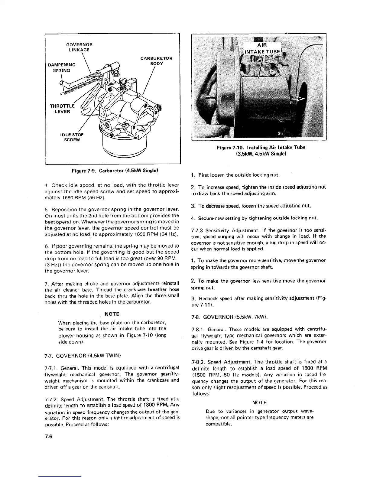
GOVERNOR
LINKAGE
\
CARBURETOR
DAMPENING
BODY
/
IDLE STOP
SCRE
Figure 7-9. Carburetor (4.5kW Single)
4. Check idle speed, at no load, with the throttle lever
against the idle speed screw and set speed to approxi-
mately 1680 RPM (56 Hz).
5. Reposition the governor spring in the governor lever.
On most units the 2nd hole from the bottom provides the
best operation. Whenever the governor spring is moved in
the governor lever, the governor speed control must be
adjusted at no load, to approximately 1890 RPM (64 Hz).
6. If poor governing remains, the spring may be moved to
the bottom hole. If the governing is good but the speed
drop from no load to full load is too great (over 90 RPM
(3 Hz)) the governor spring can be moved up one hole in
the governor lever.
7. After making choke and governor adjustments reinstall
the air cleaner base. Thread the crankcase breather hose
back thru the hole in the base plate. Align the three small
holes with the threaded holes in the carburetor.
NOTE
When placing the base plate on the carburetor,
be sure to install the air intake tube into the
blower housing as shown in Figure 7-10 (long
side down).
7-7. GOVERNOR (4.5kW TWIN)
7-7.1. General. This model is equipped with a centrifugal
flyweight mechanical governor. The governor gear/fly-
weight mechanism is mounted within the crankcase and
driven off a gear on the camshaft.
7-7.2. Speed Adjustment. The throttle shaft is fixed at a
definite length to establish a load speed of 1800 RPM. Any
variation in speed frequency changes the output of the gen-
erator. For this reason only slight re-adjustment of speed is
possible. Proceed as follows:
Figure 7-10. Installing Air Intake Tube
(3.5kW, 4.5kW Single)
1. First loosen the outside locking nut.
2. To increase speed, tighten the inside speed adjusting nut
to draw back the speed adjusting arm.
3. To d’;e’ccr”ease speed, loosen the speed adjusting nut.
4. Securenew setting by tightening outside locking nut.
7-7.3 Sensitivity Adjustment. If the governor is too sensi-
tive, speed surging will occur with change in load. If the
governor is not sensitive enough, a big drop in speed will oc-
cur when normal load is applied.
1. To make the governor more sensitive, move the governor
*
spring in togards the governor shaft.
2. To make the governor less sensitive move the governor
spring out.
3. Recheck speed after making sensitivity adjustment (Fig-
ure 7-11).
7-8. GOVERNOR (5.5kW, 7kW).
7-8.1. General. These models are equipped with centrifu-
gal flyweight type mechanical governors which are exter-
nally mounted. See Figure l-4 for location. The governor
drive gear is driven by the camshaft gear.
7-8.2. Speed Adjustment. The throttle shaft is fixed at a
definite length to establish a load speed of 1800 RPM
(1500 RPM, 50 H
z models). Any variation in speed fre-
quency changes the output of the generator. For this rea-
son only slight readjustment of speed is possible. Proceed as
follows:
NOTE
Due to variances in generator output wave-
shape, not all pointer type frequency meters are
compatible.
7-6
 Loading...

