6-6. SLIP RINGS
Slip rings acquire a glossy brown finish in normal operation.
Do not attempt to maintain a bright, newly-machined ap-
pearance. Ordinary cleaning with a dry, lint free cloth is
usually sufficient. Very fine sandpaper (#OO) may be used
to remove roughness. Use light pressure on the sandpaper.
Do not use emery or Carborundum‘ paper or cloth. Clean
out all carbon dust from the generator. If the rings are
black or pitted, remove the rotor and remove some of the
surface material by using a lathe.
6-7. EXCITER / VOLTAGE REGULATOR
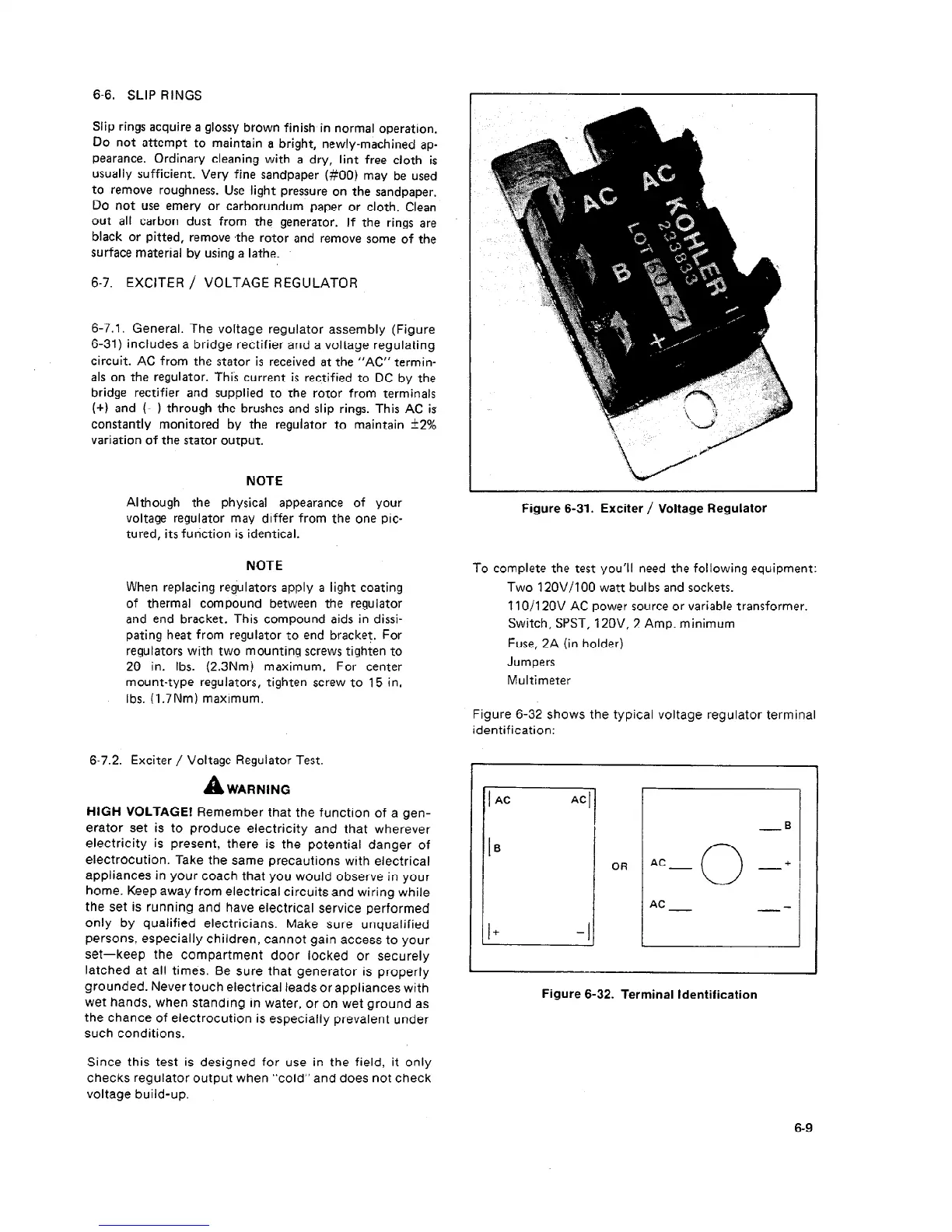
6-7.1. General. The voltage regulator assembly (Figure
6-31) includes a bridge rectifier and a voltage regulating
circuit. AC from the stator is received at the “AC” termin-
als on the regulator. Thi’s current is rectified to DC by the
bridge rectifier and supplied to the rotor from terminals
(+) and (-) through the brushes and slip rings. This AC is
constantly monitored by the regulator to maintain +2%
variation of the stator output.
NOTE
Although the physical appearance of your
voltage regulator may differ from the one pic-
tured, its fu tiction is identical.
NOTE
When replacing regulators apply a light coating
of thermal compound between the regulator
and end bracket. This compound aids in dissi-
pating heat from regulator to end bracket. For
regulators with two mounting screws tighten to
20 in. Ibs. (2.3Nm) maximum. For center
mount-type regulators, tighten screw to 15 in.
Ibs. (1.7Nm) maximum.
67.2. Exciter / Voltage Regulator Test.
A
’ WARNING
HIGH VOLTAGE! Remember that the function of a gen-
erator set is to produce electricity and that wherever
electricity is present, there is the potential danger of
electrocution. Take the same precautions with electrical
appliances in your coach that you would observe in your
home. Keep away from electrical circuits and wiring while
the set is running and have electrical service performed
only by qualified electricians. Make sure unqualified
persons, especially children, cannot gain access to your
set-keep the compartment door Iock,ed or securely
latched at all times. Be sure that generator is properly
grounded. Never touch electrical leads or appliances with
wet hands, when standing in water, or on wet ground as
the chance of electrocution is especially prevalent under
such conditions.
Since this test is designed for use in the field, it only
checks regulator output when “cold” and does not check
voltage build-up.
Figure 6-31. Exciter / Voltage Regulator
To complete the test you’ll need the following equipment:
Two 12OV/lOO watt bulbs and sockets.
11 O/l 20V AC power source or variable transformer.
Switch, PST, 12OV, 2 Amp. minimum
Fuse, 2A (in holder)
Jumpers
Multimeter
Figure 6-32 shows the typical voltage regulator terminal
identification:
OR
AC
0
+
AC
Figure 6-32. Terminal Identification
6-9
 Loading...

