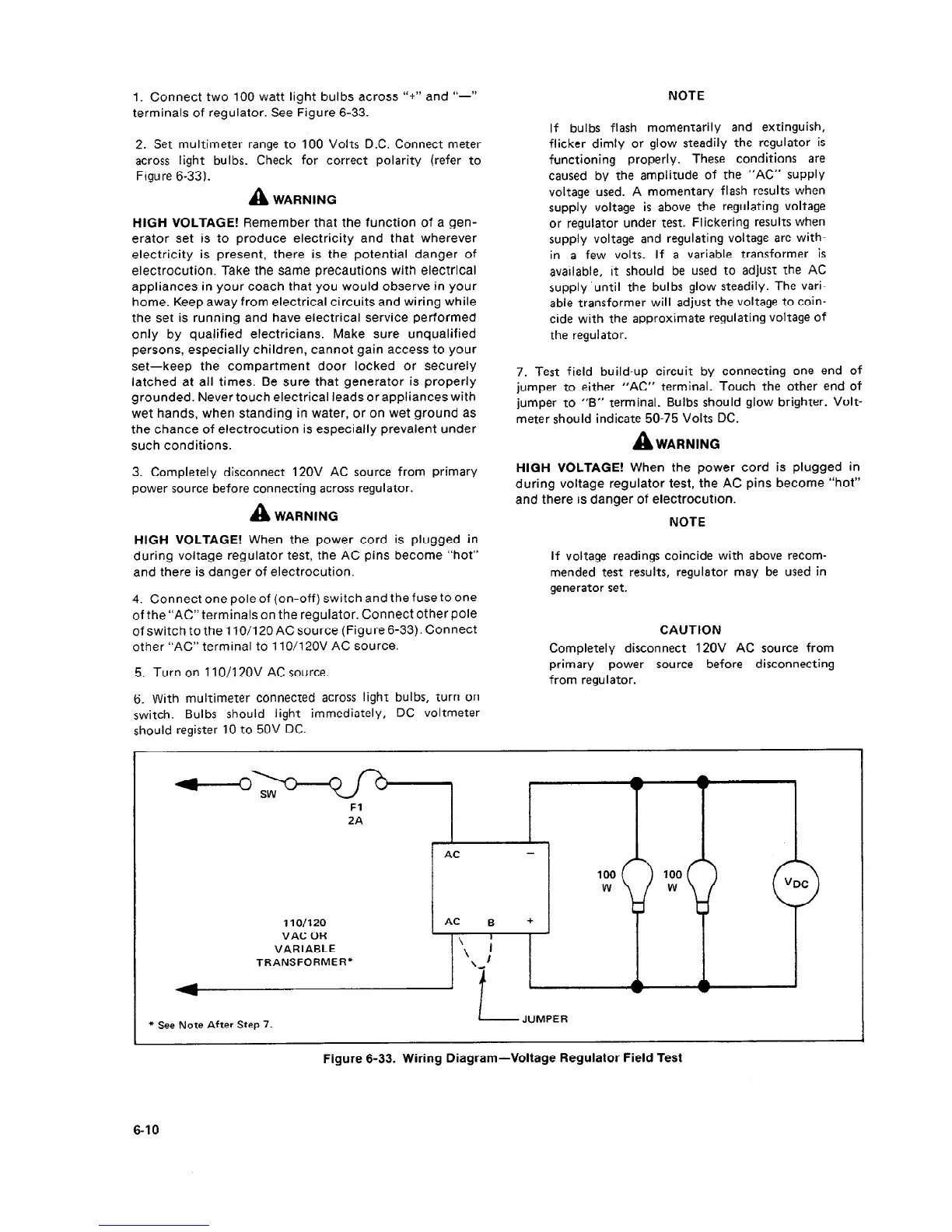
1. Connect two 100 watt light bulbs across “+” and ‘I-”
terminals of regulator. See Figure 6-33.
NOTE
2. Set multimeter range to 100 Volts DC. Connect meter
across light bulbs. Check for correct polarity (refer to
Figure 6-33).
A
WARNING
HIGH VOLTAGE! Remember that the function of a gen-
erator set is to produce electricity and that wherever
electricity is present, there is the potential danger of
electrocution. Take the same precautions with electrical
appliances in your coach that you would observe in your
home. Keep away from electrical circuits and wiring while
the set is running and have electrical service performed
only by qualified electricians. Make sure unqualified
persons, especially children, cannot gain access to your
set-keep the compartment door locked or securely
latched at all times. Be sure that generator is properly
grounded. Never touch electrical leads or appliances with
wet hands, when standing in water, or on wet ground as
the chance of electrocution is especially prevalent under
such conditions.
3. Completely disconnect IZOV AC source from primary
power source before connecting across regulator.
A
WARNING
HIGH VOLTAGE! When the power cord is plugged in
during voltage regulator test, the AC pins become “hot”
and there is danger of electrocution.
4. Connect one pole of (on-off) switch and the fuse to one
of the “AC” terminals on the regulator. Connect other pole
of switch to the 110/l 20 AC source (Figure 6-33). Connect
other “AC” terminal to 110/12OV AC source.
5. Turn on 1 IO/l 20V AC source.
6. With multimeter connected across light bulbs, turn on
switch. Bulbs should light immediately, DC voltmeter
should register 10 to 50V DC.
If bulbs flash momentarily and extinguish,
flicker dimly or glow steadily the regulator is
functioning properly.
These conditions are
caused by the amplitude of the “AC” supply
voltage used. A momentary flash results when
supply voltage is above the regulating voltage
or regulator under test. Flickering results when
supply voltage and regulating voltage are with-
in a few volts. If a variable transformer is
available, it should be used to adjust the AC
supply ‘until the bulbs glow steadily. The vari-
able transformer will adjust the voltage to coin-
cide with the approximate regulating voltage of
the regulator.
7. Test field build-up circuit by connecting one end of
jumper to either “AC” terminal. Touch the other end of
jumper to “B” terminal. Bulbs should glow brighter. Volt-
meter should indicate 50-75 Volts DC.
A
WARNING
HIGH VOLTAGE! When the power cord is plugged in
during voltage regulator test, the AC pins become “hot”
and there is danger of electrocution.
NOTE
If voltage readings coincide with above recom-
mended test results, regulator may be used in
generator set.
CAUTION
Completely disconnect IZOV AC source from
primary power
source before disconnecting
from regulator.
Fl
2A
110/120 AC B
+
VAC OR
VARIABLE
TRANSFORMER’+
* See Note After Step 7.
Figure 6-33. Wiring Diagram -Voltage Regulator Field Test
6-10
 Loading...

