).A:::‘; ::,..:, :,<4y:.:
,. ..::
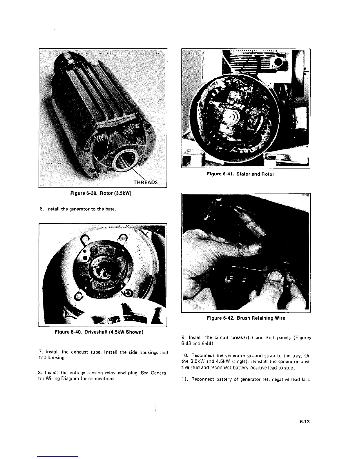
THREADS
Figure 6-39. Rotor (3.5kW)
6. Install the generator to the base.
Figure 6-41. Stator and Rotor
Figure 6-42. Brush Retaining Wire
Figure 6-40. Driveshaft (4.5kW Shown)
7. Install the exhaust tube. Install the side housings and
top housing.
8. Install the voltage sensing relay and plug. See Genera-
tor Wiring Diagram for connections.
9. Install the circuit breaker(s) and end panels (Figures
6-43 and 6-44).
10. Reconnect the generator ground strap to the tray, On
the 3.5kW and 4.5kW (single), reinstall the generator posi-
tive stud and reconnect battery positive lead to stud.
11. Reconnect battery of generator set, negative lead last.
6-13
 Loading...

