TP-6881 7/15 111Section 6 Disassembly/Reassembly
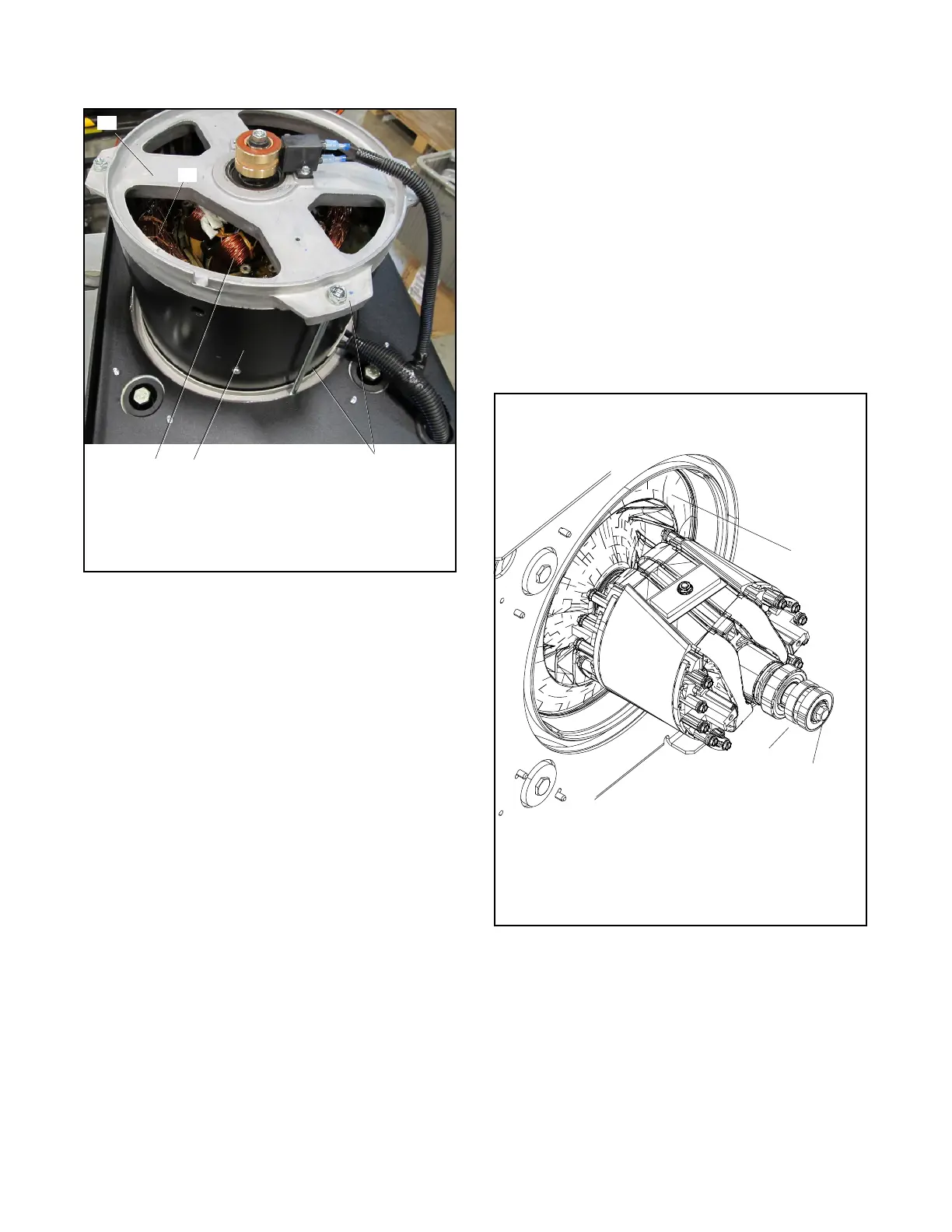
24. Remove the alternator overbolts and centering
washers. See Figure 6-9.
1. End bracket (brush assembly shown attached)
2. Stator windings (outer)
3. Rotor (inner). Also see Figure 6-10.
4. Stator shell
5. Overbolts (qty. 4)
1
3
4
5
2
Figure 6-9 Alternator Assembly
25. Using a soft-faced hammer, strike the sides of the
end bracket with medium-force blows to remove
the end bracket from the stator or remove the end
bracket from the stator using a puller. Set the end
bracket assembly aside.
26. The stator leads are routed through the bulkhead
and into the controller junction box. Carefully pull
the leads out of the junction box. Pull the leads and
conduit out through the bulkhead to free the
alternator for removal.
27. Carefully pull the stator from the rotor. See
Figure 6-9.
28. Remove the rotor as follows:
a. Loosen but do not remove the rotor thrubolt.
Use a strap wrench on the rotor to keep the
rotor from turning during loosening, if
necessary. See Figure 6-10.
b. Loosen the rotor assembly by striking the side
of the rotor with a soft-faced hammer to loosen
it from the tapered crankshaft fitting. See
Figure 6-10. Rotate the rotor and strike it on
alternate sides until it can be rocked slightly
back and forth.
Note: Do not strike the slip rings.
c. Remove the thrubolt and the rotor. Set the rotor
assembly aside.
TP6881
3
1. Adaptor plate
2. Slip rings
3. Rotor thrubolt
2
Note: Do not strike the slip rings when
removing the rotor.
1
Figure 6-10 Rotor Assembly with Thrubolt

 Loading...