TP-6881 7/15114 Section 6 Disassembly/Reassembly
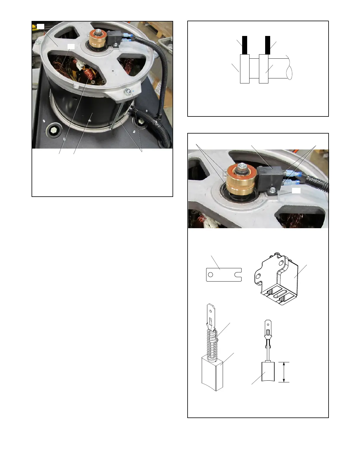
1. End bracket (brush assembly shown attached)
2. Stator windings (outer)
3. Rotor (inner). Also see Figure 6-13.
4. Stator shell
5. Overbolts (qty. 4)
1
3
4
5
2
Figure 6-14 End Bracket and Overbolt Assembly
6. Tighten the rotor thrubolt to 33 Nm (24 ft. lb.). It
may be necessary to keep the engine flywheel
from turning while torquing the rotor thrubolt.
7. Reinstall the end bracket components.
a. Inspect the brushes. If brushes show uneven
wear or are worn to less than half their original
length, replace them. See Section 5.7.
b. Install the brush holder with shim onto the end
bracket. Verify that the brushes are not sticking
in the holder.
c. Verify that the brushes are centered on the slip
rings. If required, insert spacers between the
mounting surface and brush holder to center
the brushes on the slip rings. See Figure 6-16.
See Section 5.7, Brushes, for more
information.
d. Use the cable tie to secure the brush leads to
the end bracket.
1. Correctly positioned brush
2. Incorrectly positioned brush
3. Slip rings
TP5867
Side View
1
2
3
3
Correct Incorrect
Figure 6-15 Brush Position
3
1. Slip rings
2. Brush holder
3. Brush(es)
4. Shim
5. Spring
GM80980
GM80981
Length New
19.0 mm
(0.75 in.)
Spring Not
Shown
5
3
3
GM80982
GM62996
2
4
1
4
2
Figure 6-16 Brush Assembly

 Loading...