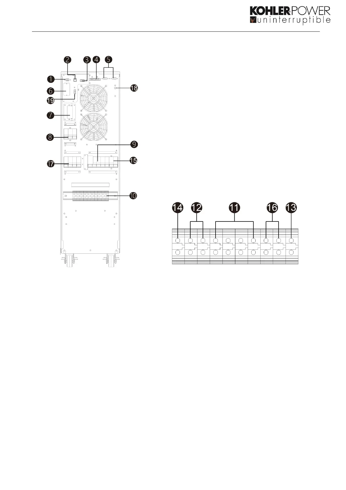
Diagram 1 Rear Panel Diagram 2: Input/Output terminals
2. USB communication port
3. Emergency power off connector (EPO
connector)
13. Input ground terminal
4. Parallel Share current port
14. Output ground terminal
15. Bypass input circuit breaker/switch
6. Intelligent slot – SNMP or DRY Port
16. Bypass input terminals
7. External battery connector/terminal
8. Line input circuit breaker/switch
9. Maintenance bypass switch
19. External Maintenance Bypass Switch connector
(EMBS)
10. Input/Output terminals (Refer to diagram 2
for the details)
 Loading...